

Appearance
Switching Probes for DUT Presence Detection
Overview
A switching probe is an electromechanical device that acts as a normally open (NO) switch inside a test fixture. When the DUT presses against the probe plunger, the internal circuit closes, signaling proper board seating. This prevents testing from starting before the DUT is loaded — protecting both the fixture and the board.
How It Works
- Normally Open (NO): No electrical connection when uncompressed — circuit reads open.
- Closer Type: DUT pushes plunger past switching point, internal contact closes circuit.
- Over-Travel: Plunger continues past switch point for proper DUT seating while maintaining closed signal.
- Signal Output: Closed circuit read by digital I/O pin to confirm DUT presence before test execution.
Wiring Options
Each probe has two contacts (inner & outer barrel) separated by a PEEK insulator. Two common wiring configurations:
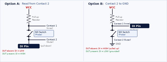
Option A reads from Contact 2 with an internal pull-down. Option B grounds Contact 2 and reads from Contact 1 — the DI pin is pulled high when open and goes low when the DUT closes the switch. Both work; choose based on your test system's I/O configuration. Debounce the digital input in software.
Probe Comparison
| Feature | Generic (KG-300K) | Ingun SKS-215 MF |
|---|---|---|
| Use Case | Dev / prototyping | Production fixtures |
| Installation | Press-fit into receptacle | Screw into KS-215 receptacle |
| Height Adjust | Fixed (3D-printed tips) | Threaded — screw in/out |
| Connection | Solder tab + receptacle | Dual solder connection points |
| Replacement | Requires desoldering | Unscrew & swap |
Generic Switching Probe — KG-300K Series
Use Case: Development and prototyping fixtures
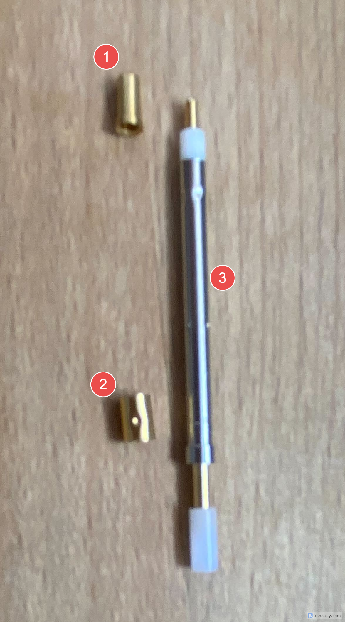
Components
- Solder Tab: Connects to the inner barrel of the switching probe
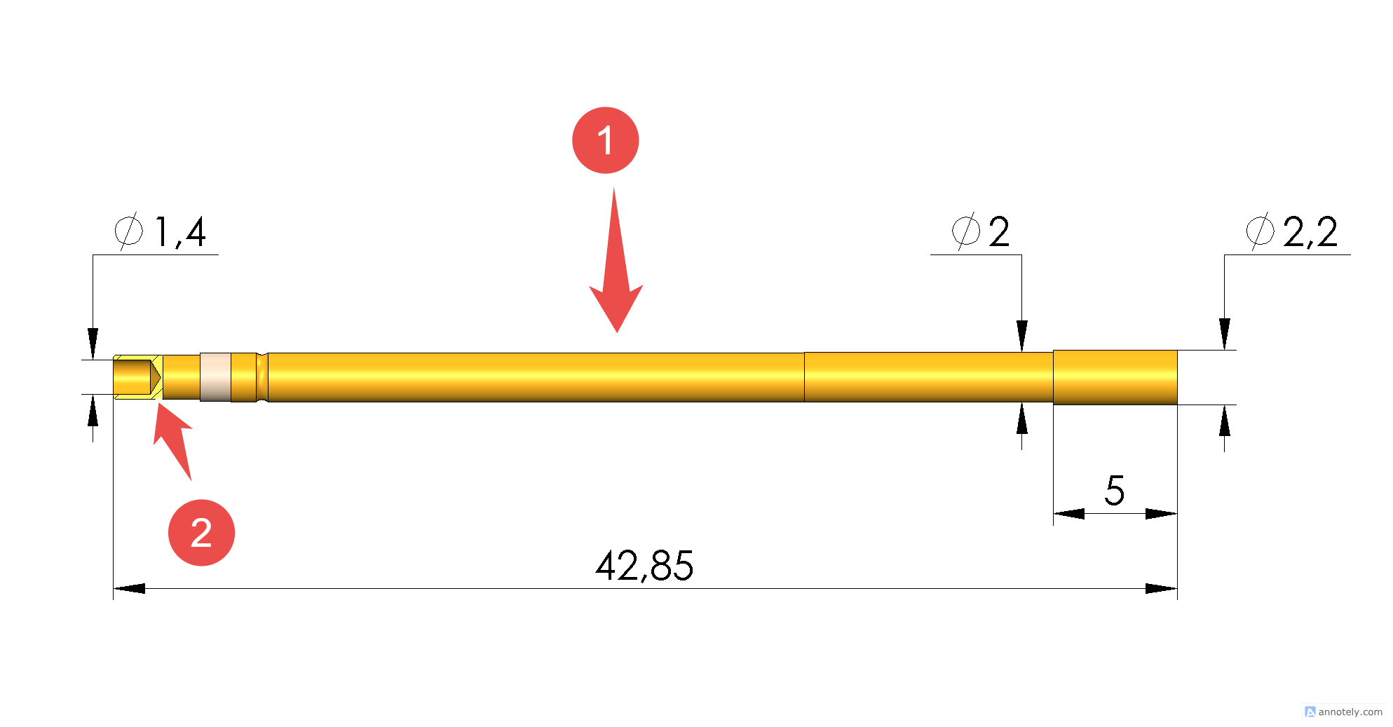
- Receptacle: Connects to the outer barrel and mounts to Probe Plate or Test Point Carrier Board
- Switching Probe: Inserts into receptacle with solder tab pressed onto bottom connection
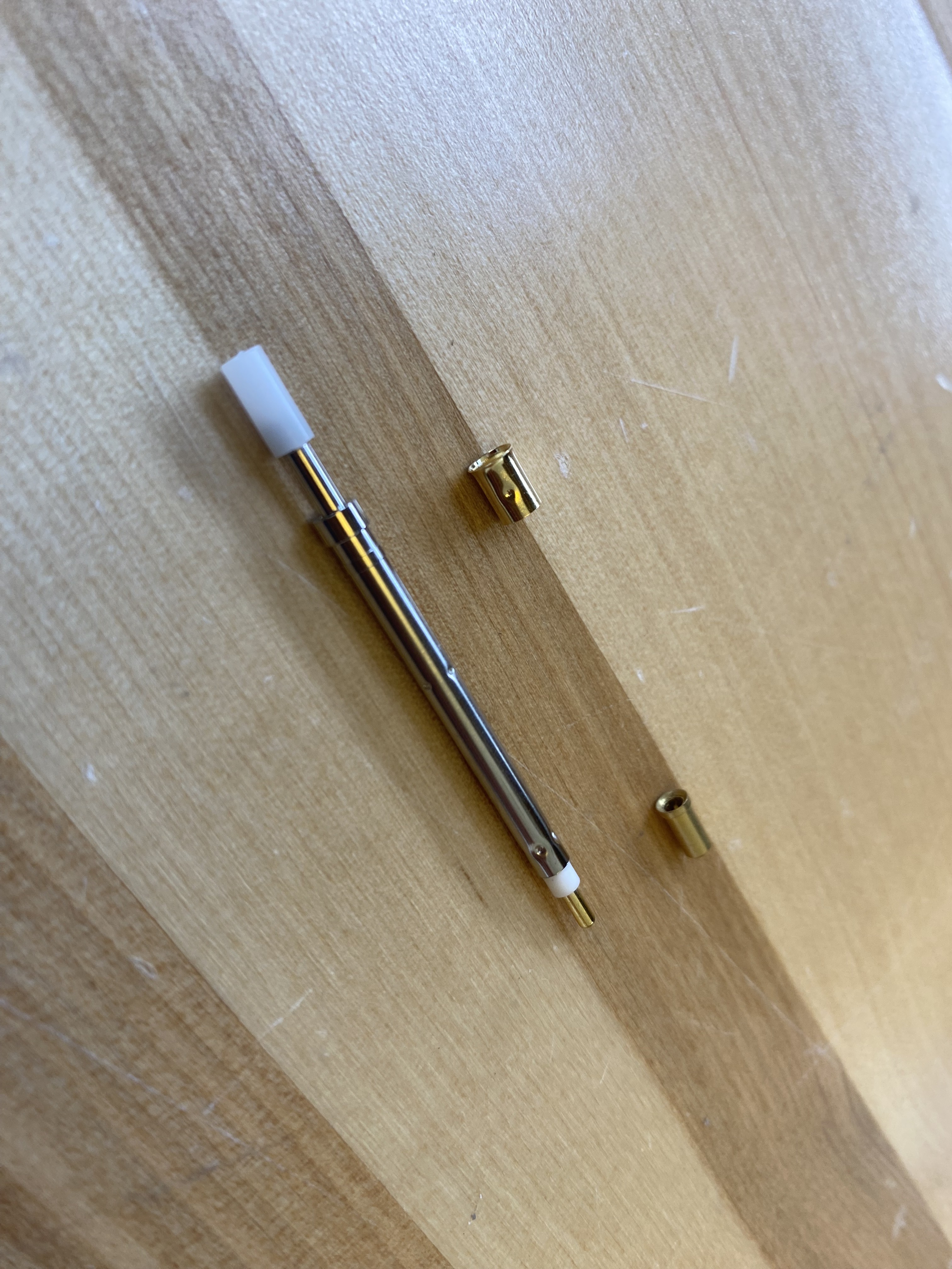 KG-300K: Switching probe (left), receptacle (top right), solder tab (bottom right)
Ingun Switching Probe — SKS-215 MF Series
The SKS-215 002 180 A 0802 MF is the recommended switching probe for production Ingun cartridge-based fixtures. It screws into a KS-215 screw-in receptacle, providing both the dual-contact electrical interface and adjustable mounting.
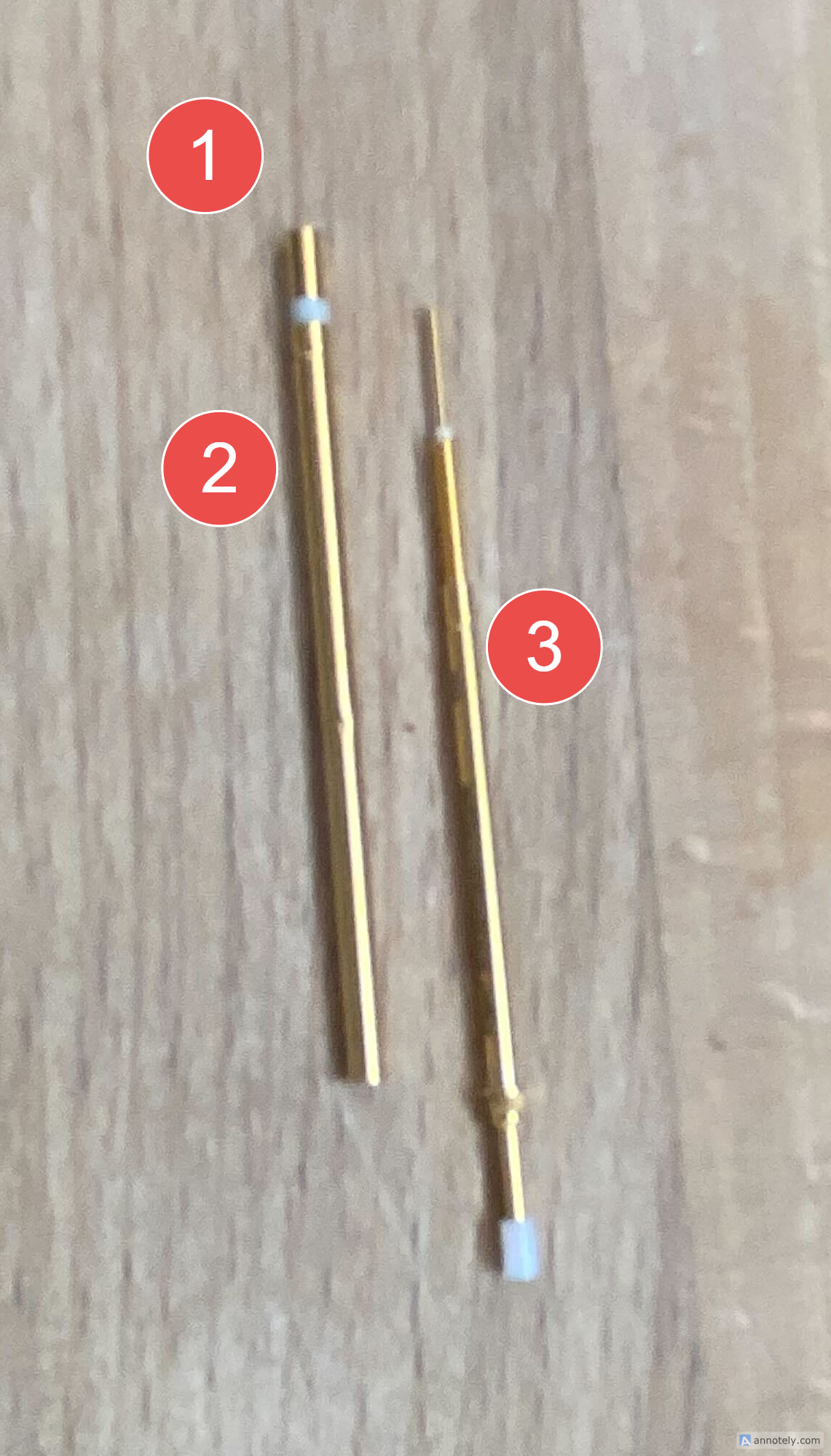
Components
- Solder Connection 1: Connects to the inner barrel of the switching probe
- Receptacle Connection 2: Connects to the outer barrel of the switching probe
- Switching Probe: Screws into receptacle with adjustable height
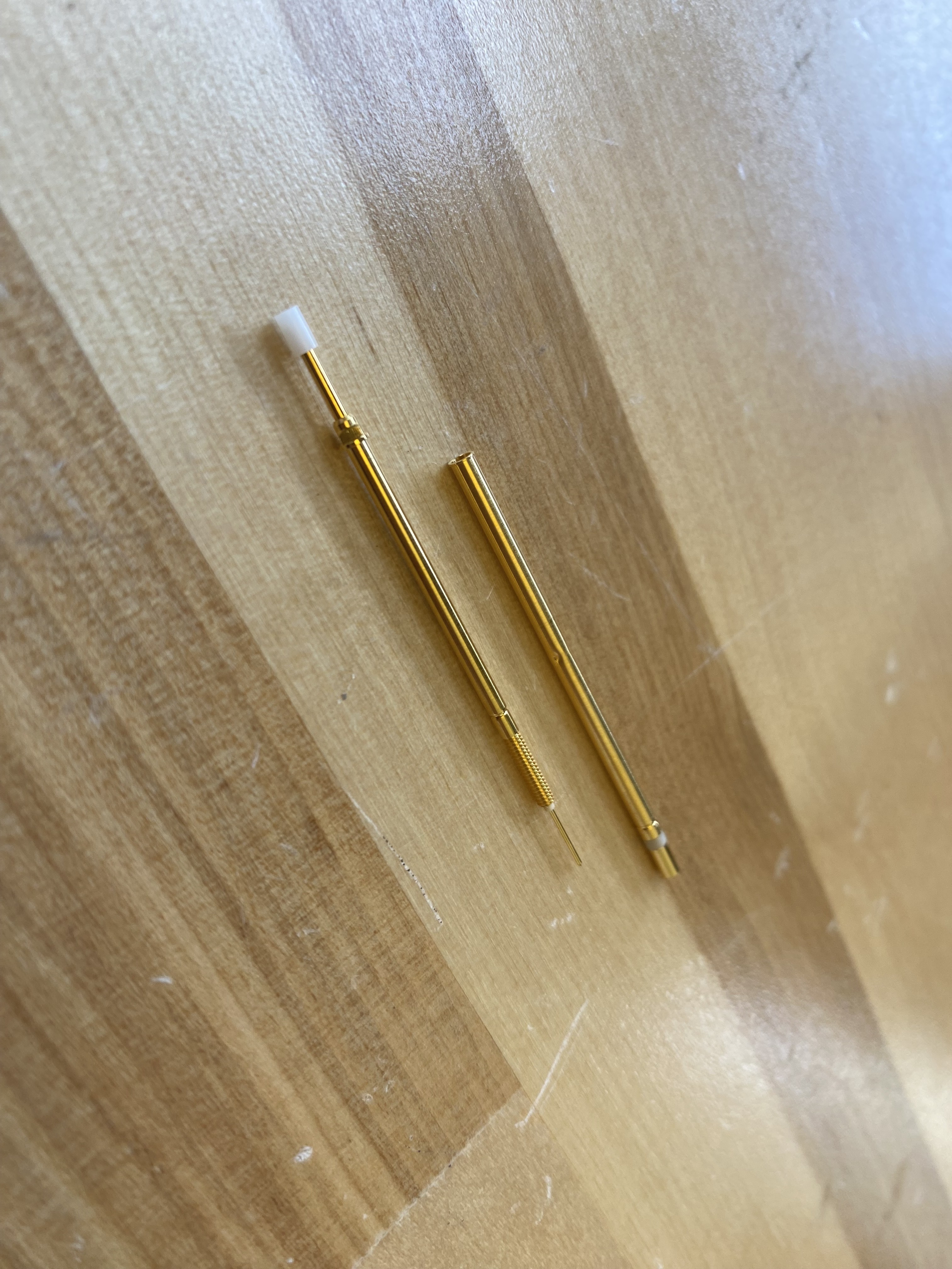 SKS-215 switching probe (bottom) and KS-215 receptacle (top)
SKS-215 Specifications (Ingun Catalogue 25.3)
| Parameter | Value |
|---|---|
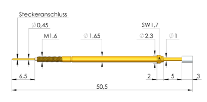
| Switch path | 1.5 mm ±0.2 |
| Working stroke | 4.0 mm |
| Max stroke | 5.0 mm |
| Spring force @ switch point | 0.8 N |
| Spring force @ working stroke | 0.8 N |
| Current rating | 3 A |
| Temp range | -40° to +80°C |
| Install height w/ KS | 10.2 mm |
| Insulator | PEEK |
Key Advantage: Adjustable Height
The SKS-215 screws into the KS-215 receptacle, so installed height and switching point can be precisely tuned by threading in or out. No shims or 3D-printed adapters needed.
Installation Guidelines
For the step-by-step procedure (probe-plate and TPCB mounting, height setting, verification), see Installing the Ingun DUT presence switch.
- Mount KS-215 receptacle securely in probe plate or TPCB to prevent rotation.
- Thread SKS-215 probe into receptacle; adjust height so switch point engages when DUT is fully seated.
- Use appropriate gauge wire when soldering connections.
TPCB Integration
The switching probe receptacle requires two separate pads on the TPCB:
- Main pad (through-hole): Sized to match the receptacle outer diameter — 3.5 mm for the Generic KG-300K receptacle, 2.4 mm for the Ingun KS-215 receptacle. The receptacle is soldered into this pad, connecting to one barrel contact.
- Secondary pad (0.1" header): A standard 0.1" (2.54 mm) header pad located nearby. A wire is soldered from this pad to the second contact — either the solder tab (Generic KG-300K) or the second receptacle connection point (Ingun SKS-215).
- Maintain adequate spacing between pads; avoid vias under mounting area.
TPCB Footprint Design
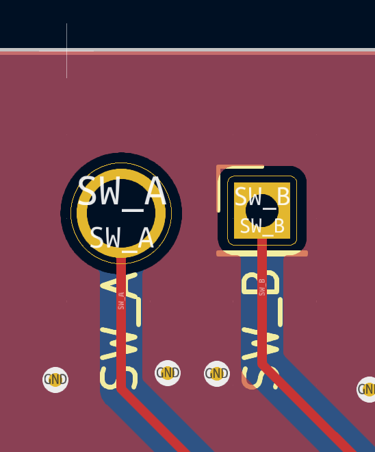
KiCad Footprint — SwitchProbe (download .kicad_mod)
| Pad | Shape | Drill | Pad Size | Purpose |
|---|---|---|---|---|
| DP-A | Circle (through-hole) | 2.1 mm | 2.7 mm | Receptacle mount (fits KS-215 @ 2.4 mm OD) |
| DP-B | Square (through-hole) | 1.0 mm | 1.7 mm | 0.1" header for wire to second contact |
Pad center-to-center spacing: ~3.5 mm.
Probe and Receptacle Components
Switching Probe: Plastic tip that actuates mechanical switch when plunger is pressed
Receptacle: Two-contact design with plastic separation between contacts
Troubleshooting
| Symptom | Likely Cause | Fix |
|---|---|---|
| False positive | Probe stuck closed; contamination | Clean or replace |
| False negative | Height too low; poor contact | Adjust height |
| Intermittent | Loose solder; worn probe | Re-solder; replace |
Maintenance Schedule
Daily: Visual inspection | Weekly: Continuity | Monthly: Clean tips | Quarterly: Replace probes
Panels
When a DUT is panelized, the fixture carries one presence switch per device, each selected and placed in the test configuration. The fixture BOM counts every switch by quantity. All switches sit on the primary probe side of the fixture.