Switching Probes for DUT Presence Detection
Overview
A switching probe is an electromechanical device that acts as a normally open (NO) switch inside a test fixture. When the DUT presses against the probe plunger, the internal circuit closes, signaling proper board seating. This prevents testing from starting before the DUT is loaded — protecting both the fixture and the board.
How It Works
- Normally Open (NO): No electrical connection when uncompressed — circuit reads open.
- Closer Type: DUT pushes plunger past switching point, internal contact closes circuit.
- Over-Travel: Plunger continues past switch point for proper DUT seating while maintaining closed signal.
- Signal Output: Closed circuit read by digital I/O pin to confirm DUT presence before test execution.
Wiring Options
Each probe has two contacts (inner & outer barrel) separated by a PEEK insulator. Two common wiring configurations:
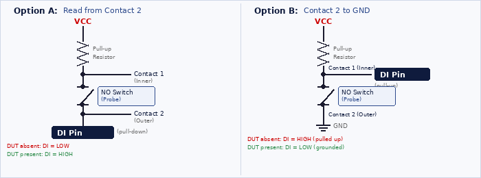
Option A reads from Contact 2 with an internal pull-down. Option B grounds Contact 2 and reads from Contact 1 — the DI pin is pulled high when open and goes low when the DUT closes the switch. Both work; choose based on your test system's I/O configuration. Debounce the digital input in software.
Probe Comparison
| Feature | Generic (KG-300K) | Ingun SKS-215 MF |
|---|---|---|
| Use Case | Dev / prototyping | Production fixtures |
| Installation | Press-fit into receptacle | Screw into KS-215 receptacle |
| Height Adjust | Fixed (3D-printed tips) | Threaded — screw in/out |
| Connection | Solder tab + receptacle | Dual solder connection points |
| Replacement | Requires desoldering | Unscrew & swap |
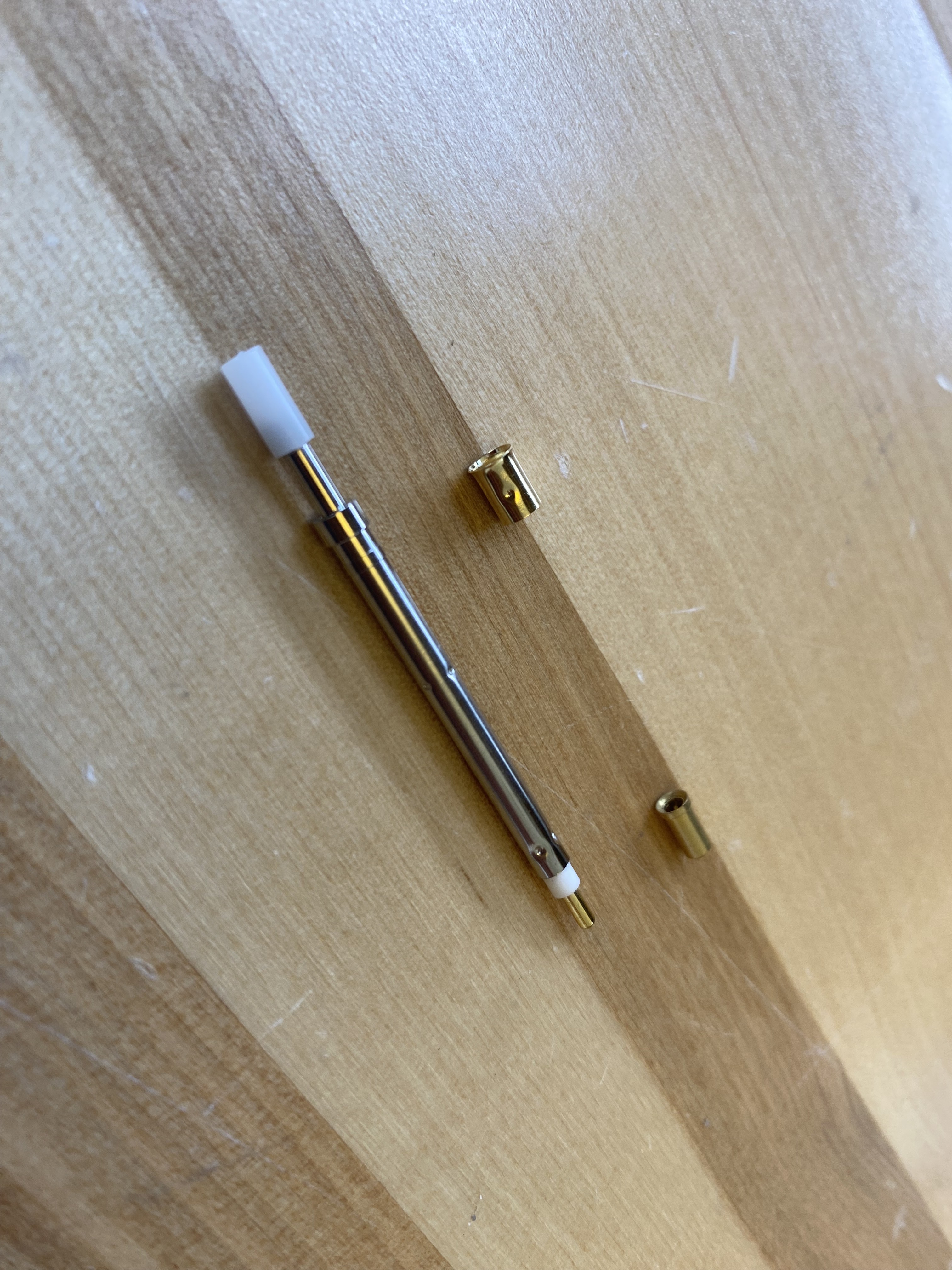
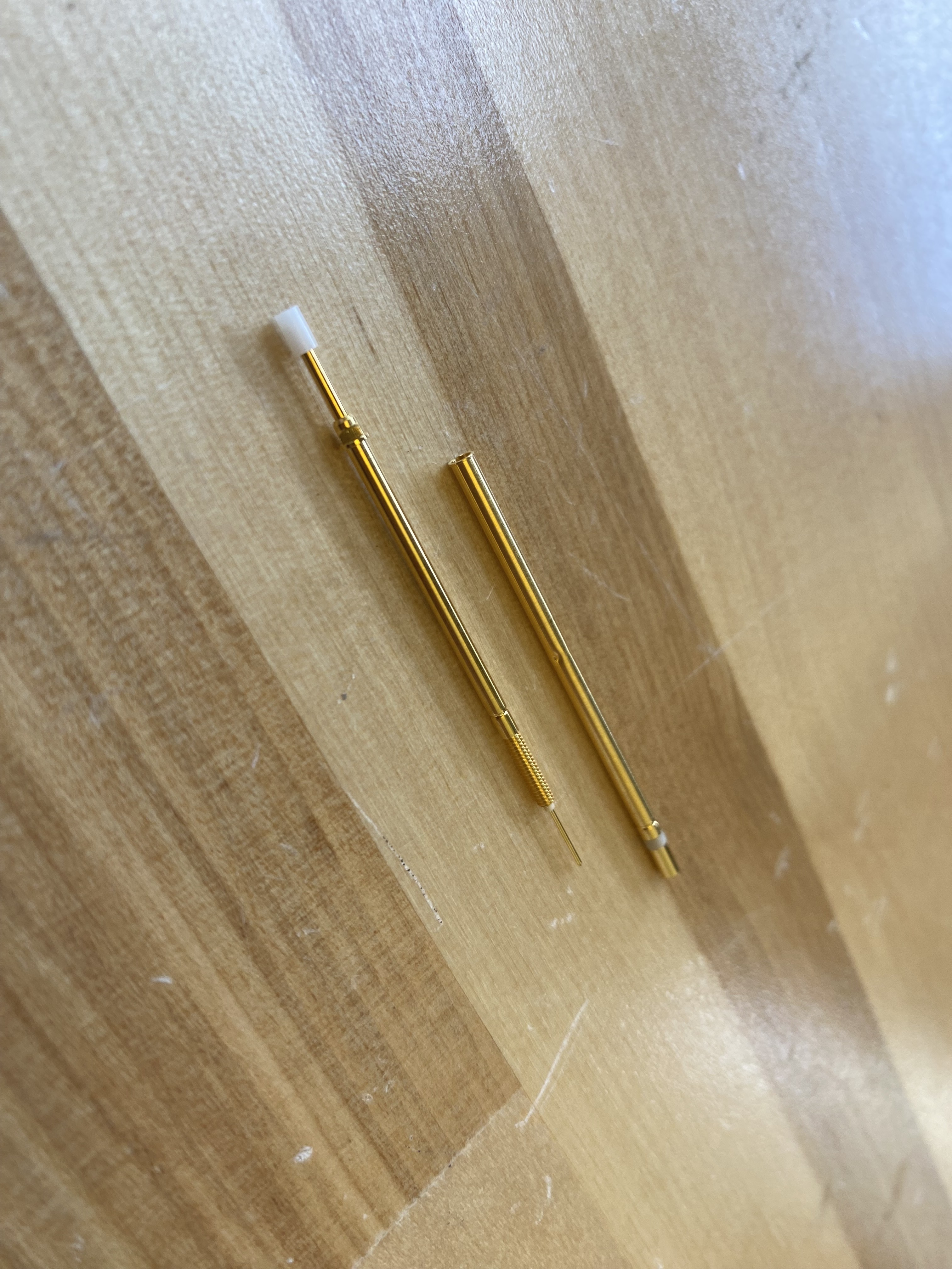
Generic Switching Probe — KG-300K Series
Use Case: Development and prototyping fixtures
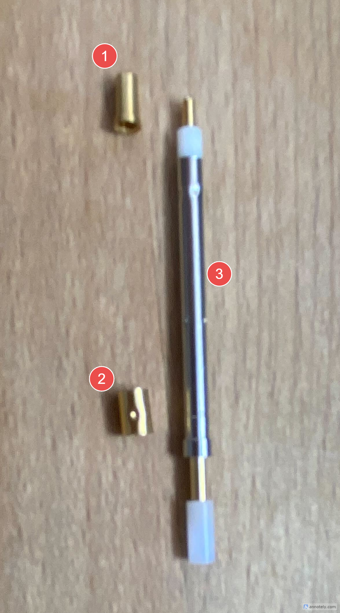
Components
- Solder Tab: Connects to the inner barrel of the switching probe
- Receptacle: Connects to the outer barrel and mounts to Probe Plate or Test Point Carrier Board
- Switching Probe: Inserts into receptacle with solder tab pressed onto bottom connection
 KG-300K: Switching probe (left), receptacle (top right), solder tab (bottom right)
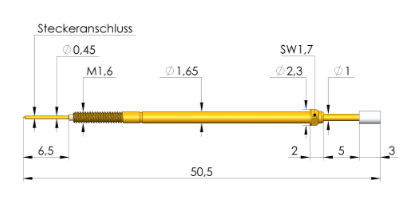
Ingun Switching Probe — SKS-215 MF Series
The SKS-215 002 180 A 0802 MF is the recommended switching probe for production Ingun cartridge-based fixtures. It screws into a KS-215 screw-in receptacle, providing both the dual-contact electrical interface and adjustable mounting.
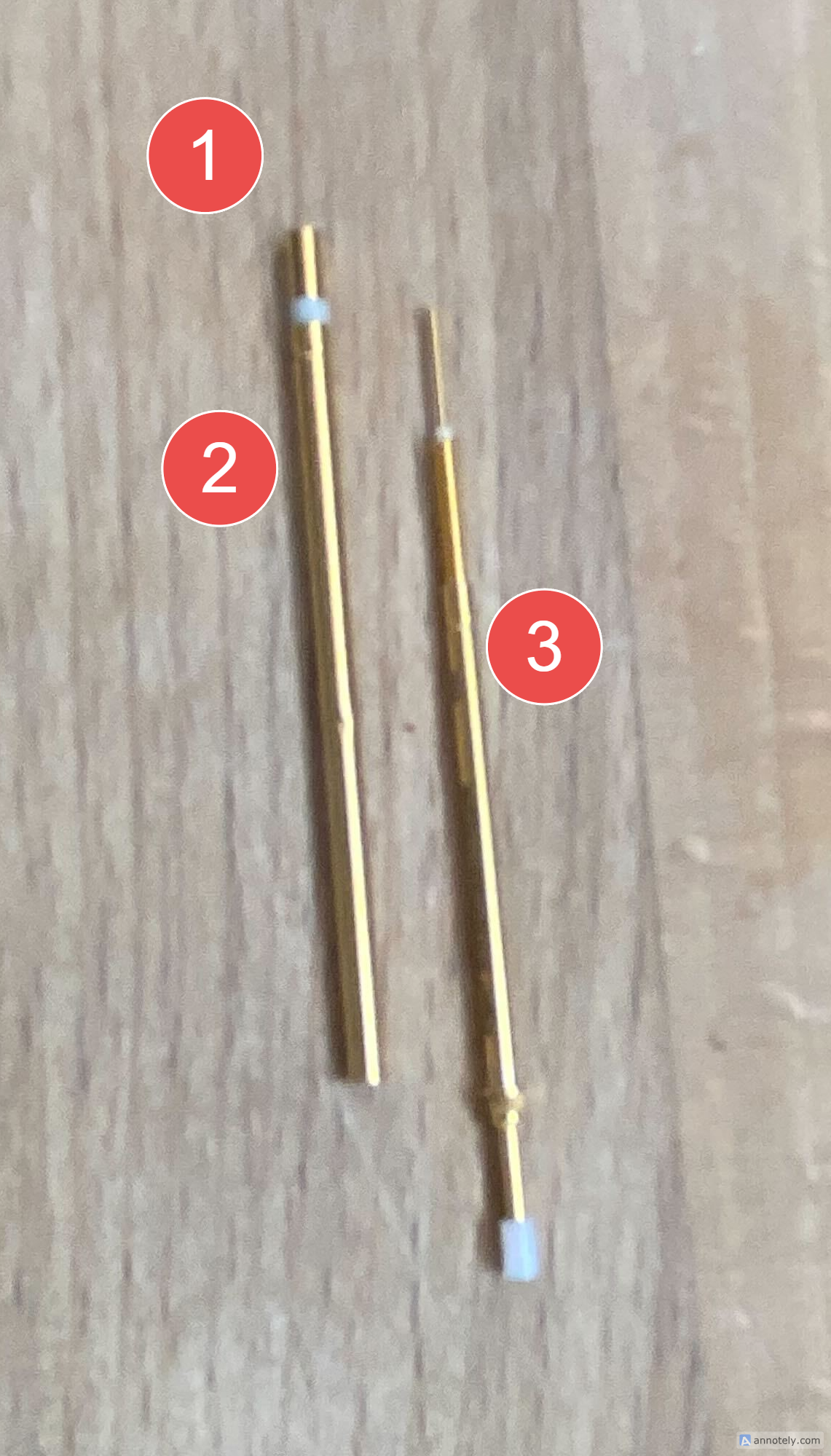
Components
- Solder Connection 1: Connects to the inner barrel of the switching probe
- Receptacle Connection 2: Connects to the outer barrel of the switching probe
- Switching Probe: Screws into receptacle with adjustable height
 SKS-215 switching probe (bottom) and KS-215 receptacle (top)
SKS-215 Specifications (Ingun Catalogue 25.3)
| Parameter | Value |
|---|---|
| Switch path | 1.5 mm ±0.2 |
| Working stroke | 4.0 mm |
| Max stroke | 5.0 mm |
| Spring force @ switch point | 0.8 N |
| Spring force @ working stroke | 0.8 N |
| Current rating | 3 A |
| Temp range | -40° to +80°C |
| Install height w/ KS | 10.2 mm |
| Insulator | PEEK |
Key Advantage: Adjustable Height
The SKS-215 screws into the KS-215 receptacle, so installed height and switching point can be precisely tuned by threading in or out. No shims or 3D-printed adapters needed.
Installation Guidelines
- Mount KS-215 receptacle securely in probe plate or TPCB to prevent rotation.
- Thread SKS-215 probe into receptacle; adjust height so switch point engages when DUT is fully seated.
- Use appropriate gauge wire when soldering connections.
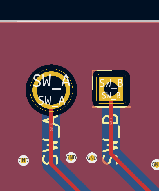
TPCB Integration
The switching probe receptacle requires two separate pads on the TPCB:
- Main pad (through-hole): Sized to match the receptacle outer diameter — 3.5 mm for the Generic KG-300K receptacle, 2.4 mm for the Ingun KS-215 receptacle. The receptacle is soldered into this pad, connecting to one barrel contact.
- Secondary pad (0.1" header): A standard 0.1" (2.54 mm) header pad located nearby. A wire is soldered from this pad to the second contact — either the solder tab (Generic KG-300K) or the second receptacle connection point (Ingun SKS-215).
- Maintain adequate spacing between pads; avoid vias under mounting area.
TPCB Footprint Design
KiCad Footprint — SwitchProbe (download .kicad_mod)
| Pad | Shape | Drill | Pad Size | Purpose |
|---|---|---|---|---|
| DP-A | Circle (through-hole) | 2.1 mm | 2.7 mm | Receptacle mount (fits KS-215 @ 2.4 mm OD) |
| DP-B | Square (through-hole) | 1.0 mm | 1.7 mm | 0.1" header for wire to second contact |
Pad center-to-center spacing: ~3.5 mm.
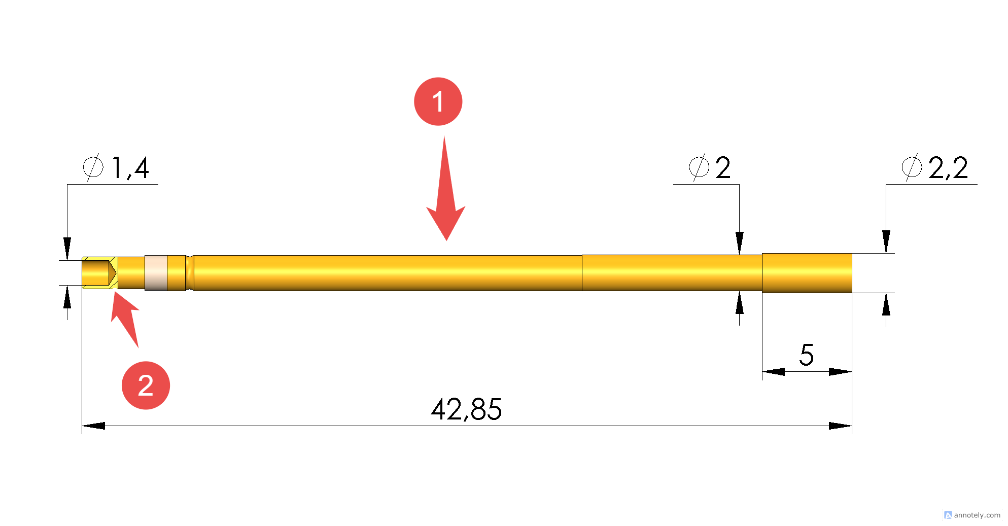
Probe and Receptacle Components
Switching Probe: Plastic tip that actuates mechanical switch when plunger is pressed
Receptacle: Two-contact design with plastic separation between contacts
Troubleshooting
| Symptom | Likely Cause | Fix |
|---|---|---|
| False positive | Probe stuck closed; contamination | Clean or replace |
| False negative | Height too low; poor contact | Adjust height |
| Intermittent | Loose solder; worn probe | Re-solder; replace |
Maintenance Schedule
Daily: Visual inspection | Weekly: Continuity | Monthly: Clean tips | Quarterly: Replace probes