Dev Fixture Design Guidelines
This page provides best practices and component recommendations for building reliable Dev series test fixtures. Follow these guidelines to ensure optimal performance, ease of assembly, and cost-effectiveness.
Recommended Components
Guide Pins
- Spring guide pins are the preferred method for accurately locating the DUT (Device Under Test) within the fixture.
- If the DUT’s locating holes are smaller than 3mm (minimum 2.5mm), use a custom cradle for positioning.
- Cradles should be mounted to GP2-T or GP2-TL guide pins using M3 screws for secure and repeatable placement.
Pressure Pins
- Use 45mm pressure pins for all Dev fixtures.
- Pressure pins are attached to the pressure plate with M3 x 10mm screws, providing consistent downward force on the DUT.
Receptacles and Probes
- Generic receptacles and probes are recommended for Dev fixtures, offering the best balance of cost and performance for short-lifecycle applications.
- Premium options are available, but are generally unnecessary due to the fixture’s limited lifespan.
- Use the "2" style collar (2.5mm collar height) for compatibility with standard pressure pin lengths.
- If using a different collar height, adjust the pressure pin length accordingly.
- Probe tip selection:
- Use LM2 tips for standard test points.
- Use A2 tips for populated through-hole connections.
Probe Plate
- Design the probe plate with cutouts to avoid interference with tall components on the DUT, ensuring proper fit and probe access.
Fixture Assembly Instructions
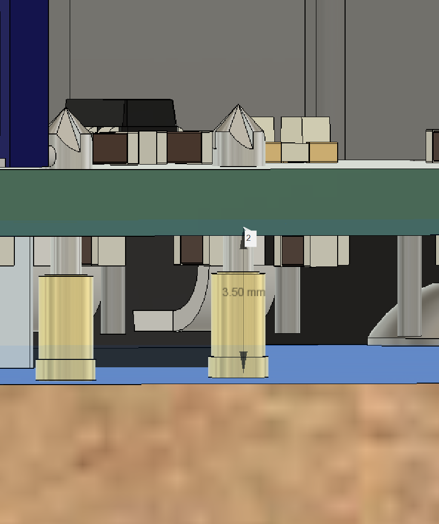
DUT Mating Height
- Position the DUT so that its bottom surface is 3.5mm above the probe plate. This height is optimized for use with a 45mm pressure pin and a 2.5mm collar.
- Use a mounting or tooling hole on the DUT for precise and repeatable alignment.