DUT Locating
Proper PCBA positioning is critical for creating a reliable test fixture. Here are our recommended approaches for accurately locating your device under test (DUT).
Spring Guide Pins
Spring guide pins are our preferred method for DUT locating. These consist of a conical tip mounted on a spring-loaded barrel that installs directly into the fixture's probe plate. The spring mechanism and conical design accommodates hole diameters from ~2.5mm to 5mm, making them versatile for various mounting and tooling holes.
For our Dev Pro series fixtures, we use cost-effective generic pins like the GP-2UL: 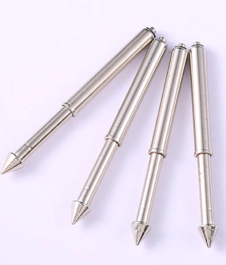
For production fixtures, we utilize Misumi PGPU guide pins. While more expensive, these offer superior durability and precision: 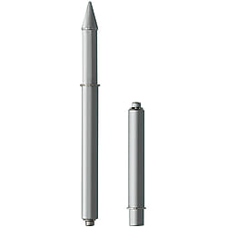
Browse our complete selection of guide pins here
Tooling Pins
For applications requiring smaller locating holes or side actuation, we recommend tooling pins from trusted manufacturers like Ingun, McMaster, or Misumi. In production fixtures, these pins mount directly to the moving plate.
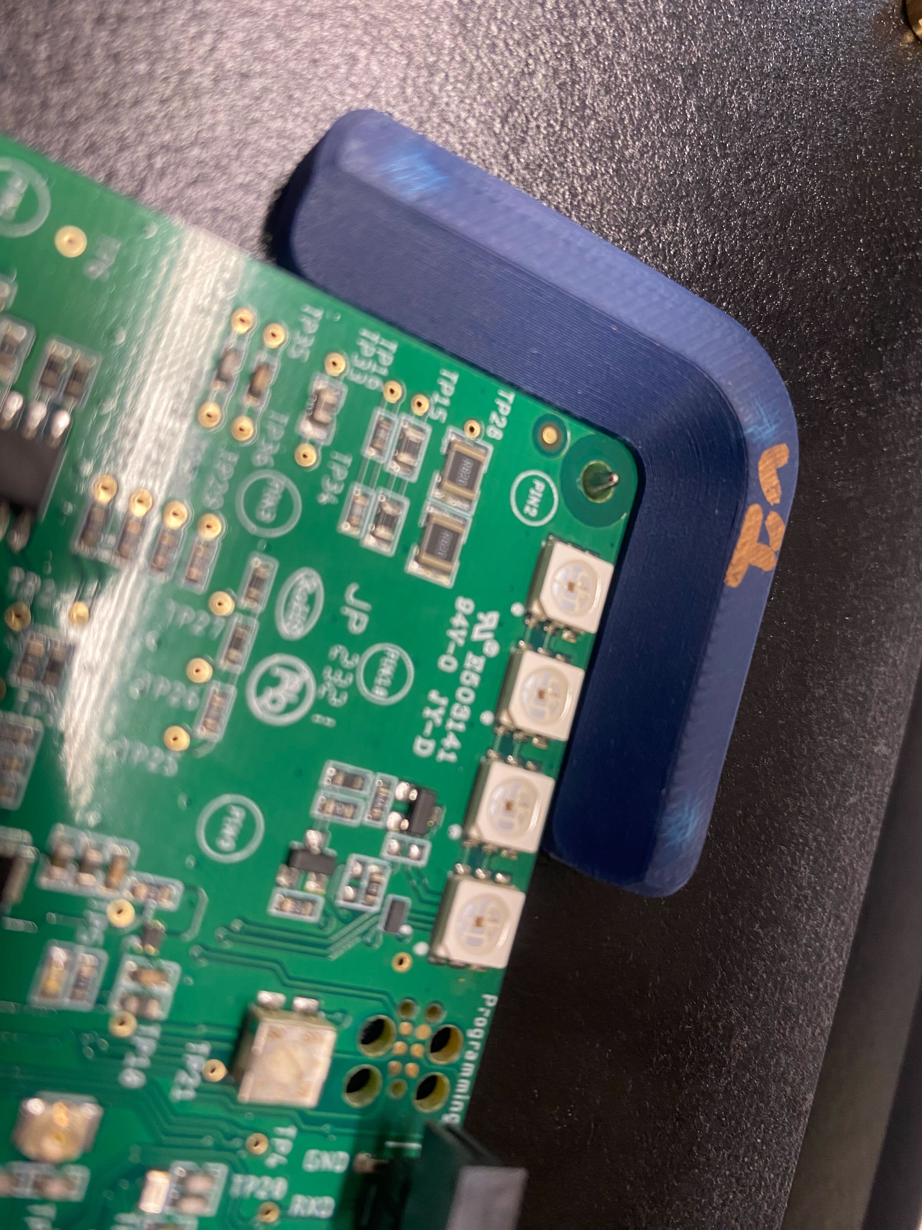
Cradles
When a DUT lacks mounting or tooling holes, custom cradles provide reliable positioning. We typically manufacture these from either 3D printed PETG/PLA or machined Acetal (Delrin).
Here's an example of a 3D printed cradle: 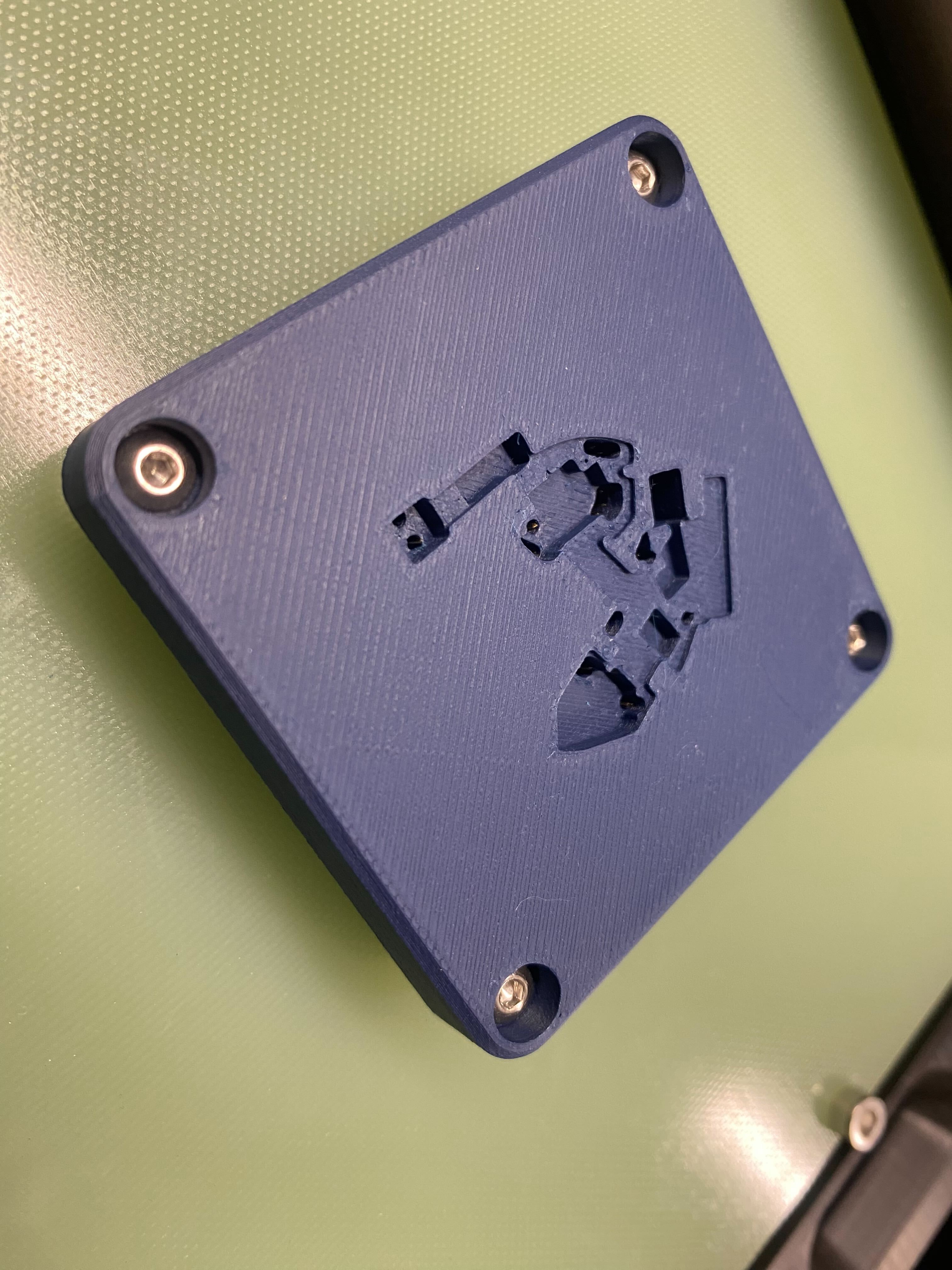
Design Specifications
| Parameter | Description | Specification |
|---|---|---|
| Cradle Thickness | Bottom of fixture to top of DUT | 10mm |
| Min Cradle Offset (Machined) | Bottom of fixture to bottom of DUT | 0.1mm |
| Min Cradle Offset (V-Groove) | Bottom of fixture to bottom of DUT | 0.2mm |
| Probe Hole Diameter | Probe tip clearance | probe_tip_diameter + 1mm |
| Guide Pin Clearance | Guide pin passage | guide_pin_diameter + 1mm |
Design Best Practices
- Start with accurate source files:
- STEP model of the DUT or
- DXF file of the PCB outline
- Use these to create precise offset paths
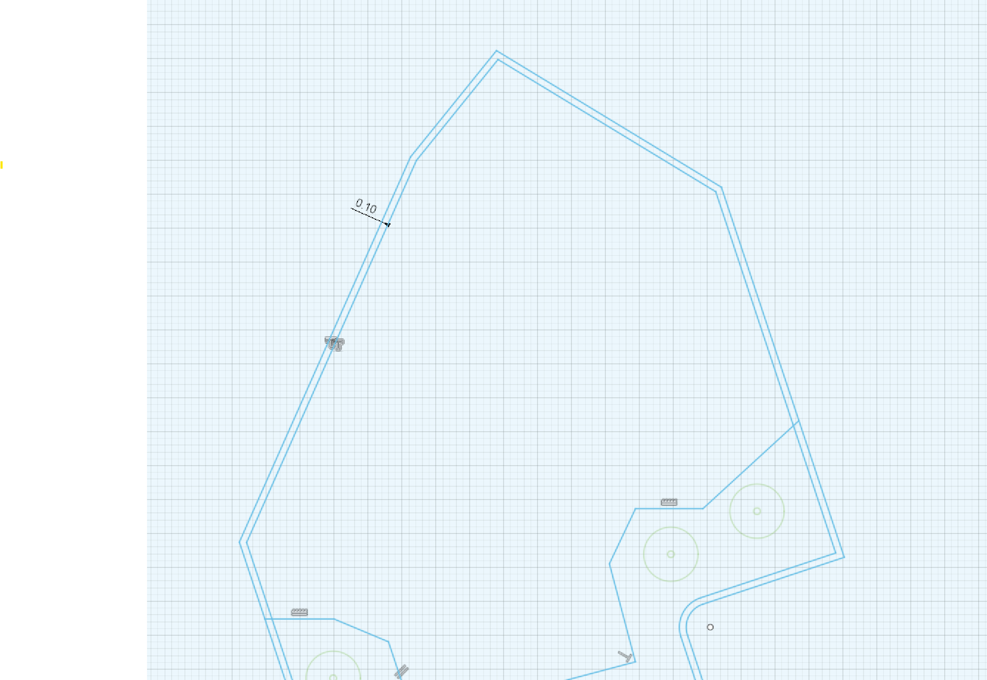
- Account for PCB manufacturing method:
- Machined PCBs: Use 0.1mm offset
- V-grooved PCBs: Use minimum 0.2mm offset
- Size probe holes appropriately:
- Diameter = probe tip diameter + 1mm
- Include guide pin clearance when needed:
- Diameter = guide pin diameter + 1mm
- Add chamfered edges to assist DUT placement
Pre-Centering Guides
Pre-centering guides facilitate smooth DUT placement and alignment. These partial guides mount to the fixture with screws and feature chamfered edges for easy DUT positioning.
Typically mounted with M3 screws from the moving plate's underside, these guides ensure proper alignment with locating pins while maintaining efficient workflow.