Receptacles
Receptacles are used to make it easy to replace damaged or worn out test probes/pogo-pins. Receptacles typically have a collar, and can be mounted either with the collar setting the height, or press fit into the probe plate of a fixture.

Above is an example of an Ingun KS-075 WL Receptacle.
Receptacle Styles
There are three common parameters that define a test probe receptacle:
- Pitch: The distance between the centers of two adjacent pins.
- Collar Height: The distance from the top of the receptacle to the bottom of the collar.
- Connector Type: The type of electrical connector that is used to connect the receptacle to instrumentation.
Pitch
The pitch of a receptacle is the distance between the centers of two adjacent pins. This is matched to the pitch of the test points on the Device Under Test (DUT).
Receptacles and Probes with a larger pitch tend to be more robust and less likely to be damaged during use, while smaller pitches are more susceptible to damage.
Pitches are commonly defined in mils (1/1000 of an inch). The most common pitches are:
- 50 mils (1.27 mm)
- 75 mils (1.905 mm)
- 100 mils (2.54 mm)
Smaller and larger pitches are also available, but are less common.
Here's the minimum center spacing data converted to a markdown table:
Minimum Center Spacing
The following charts detail the minimum recommended center-to-center spacing for conventional receptacles. Note: headed probes may require larger spacing depending on their diameter.
| CENTERS | 0.039 [1.00] | 0.050 [1.27] | 0.075 [1.91] | 0.100 [2.54] | 0.125 [3.18] | 0.156 [3.96] | 0.187 [4.75] |
|---|---|---|---|---|---|---|---|
| 0.039 [1.00] | 0.039 [1.00] | 0.043 [1.09] | 0.052 [1.32] | 0.060 [1.53] | 0.071 [1.80] | 0.078 [1.98] | 0.095 [2.41] |
| 0.050 [1.27] | 0.043 [1.09] | 0.048 [1.22] | 0.057 [1.45] | 0.064 [1.63] | 0.077 [1.96] | 0.084 [2.13] | 0.101 [2.57] |
| 0.075 [1.91] | 0.052 [1.32] | 0.057 [1.45] | 0.068 [1.73] | 0.075 [1.91] | 0.087 [2.21] | 0.094 [2.39] | 0.111 [2.82] |
| 0.100 [2.54] | 0.060 [1.53] | 0.064 [1.63] | 0.075 [1.91] | 0.085 [2.16] | 0.098 [2.49] | 0.105 [2.67] | 0.122 [3.10] |
| 0.125 [3.18] | 0.071 [1.80] | 0.077 [1.96] | 0.087 [2.21] | 0.098 [2.49] | 0.111 [2.82] | 0.118 [3.00] | 0.135 [3.43] |
| 0.156 [3.96] | 0.078 [1.98] | 0.084 [2.13] | 0.094 [2.39] | 0.105 [2.67] | 0.118 [3.00] | 0.133 [3.38] | 0.150 [3.81] |
| 0.187 [4.75] | 0.095 [2.41] | 0.101 [2.57] | 0.111 [2.82] | 0.122 [3.10] | 0.135 [3.43] | 0.150 [3.81] | 0.166 [4.21] |
Note: Values are in inches with millimeter equivalents in brackets [mm]
Collar Height
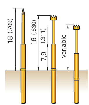
The collar height of a receptacle is the distance from the top of the receptacle to the bottom of the collar. This can be used to vary the height of the receptacle relative to the probe plate of a fixture. This, in a combination with the working stroke of the test probe, determines the probing height for the fixture.
It is common to use the collar as a way to set the installation height of the receptacle, but it is also possible to use the press-fit the mount the receptacle, where the collar is pressed into the probe plate of the fixture.

Above, the probes on the left are mounted with the collar set to the maximum height, while the probe on the right is press-fit into the probe plate.
Connector Type
Receptacles can be connected to using several different styles, the most common being:
Wirewrap Post, a square post that can be wirewrapped, these also work well with Female Dupont connectors for quick prototyping.

Solder Cup, a cup that a wire can be soldered to.

Wired, a wire (typically a 32AWG wire wrap wire) that is crimped to the receptacle.
Wireless, these receptacles feature a spring-loaded pin on the bottom of the receptacle that makes contact with a Test Point Carrier Board (TPCB).

Common Drill Sizes
Note: These drill sizes are for G10 or FR4 material. Exact diameter may vary depending on the material used.
| Receptacle | Collar Mount Drill Diameter | Press-Fit Mount Drill Diameter |
|---|---|---|
| Generic R50 | 0.95 mm | N/A |
| Generic R75 | 1.35 mm | N/A |
| Generic R100 | 1.7 mm | N/A |
| Generic KG-300 | N/A | 3.4mm |
| Centalic RQ50 | 1.0 mm | N/A |
| Centalic RE75 | 1.35 mm | N/A |
| Centalic RQ100 | 1.7 mm | N/A |
| Ingun KS-550 WL | 1.04 mm | 1.05 mm |
| Ingun KS-075 WL | 1.3 mm | 1.4 mm |
| Ingun KS-100 WL | 1.7 mm | 1.75 mm |
| Ingun KS-215 M1.6F | 2.0 mm | N/A |