Creating a Design for Test Report
Create a new report
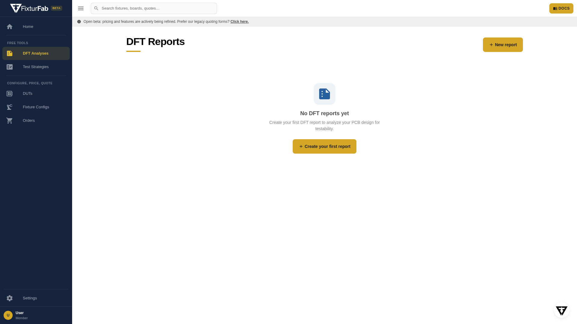
To create a new report, open DFT Analyses in the sidebar and click New Report — or click Run now on the DFT Analysis card on the Studio home page.
Name the report (a default name is generated for you) and select your test point file. Valid extensions are .d356, .ipc, or .csv. See this page for help exporting an IPC-D-356 netlist.
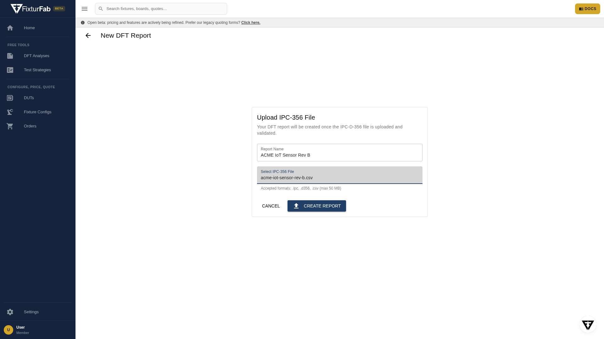
Click Create Report. The file is processed and the report wizard opens.
Step 1: Upload DUT Information
The first wizard step shows the report name and the processed file, with a preview of all test records rendered in the viewer. You can rename the report or replace the file here.
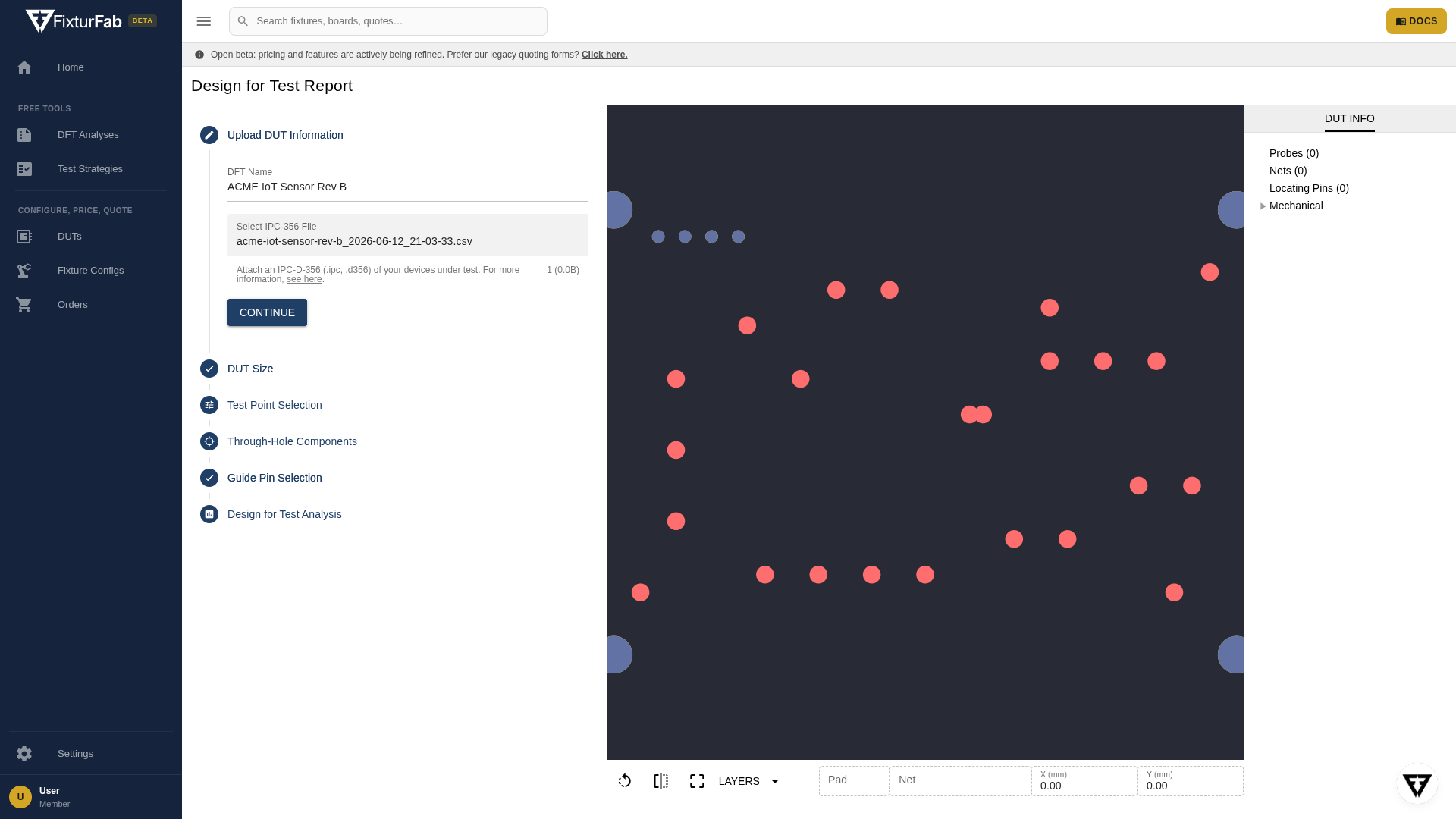
Press Continue to proceed.
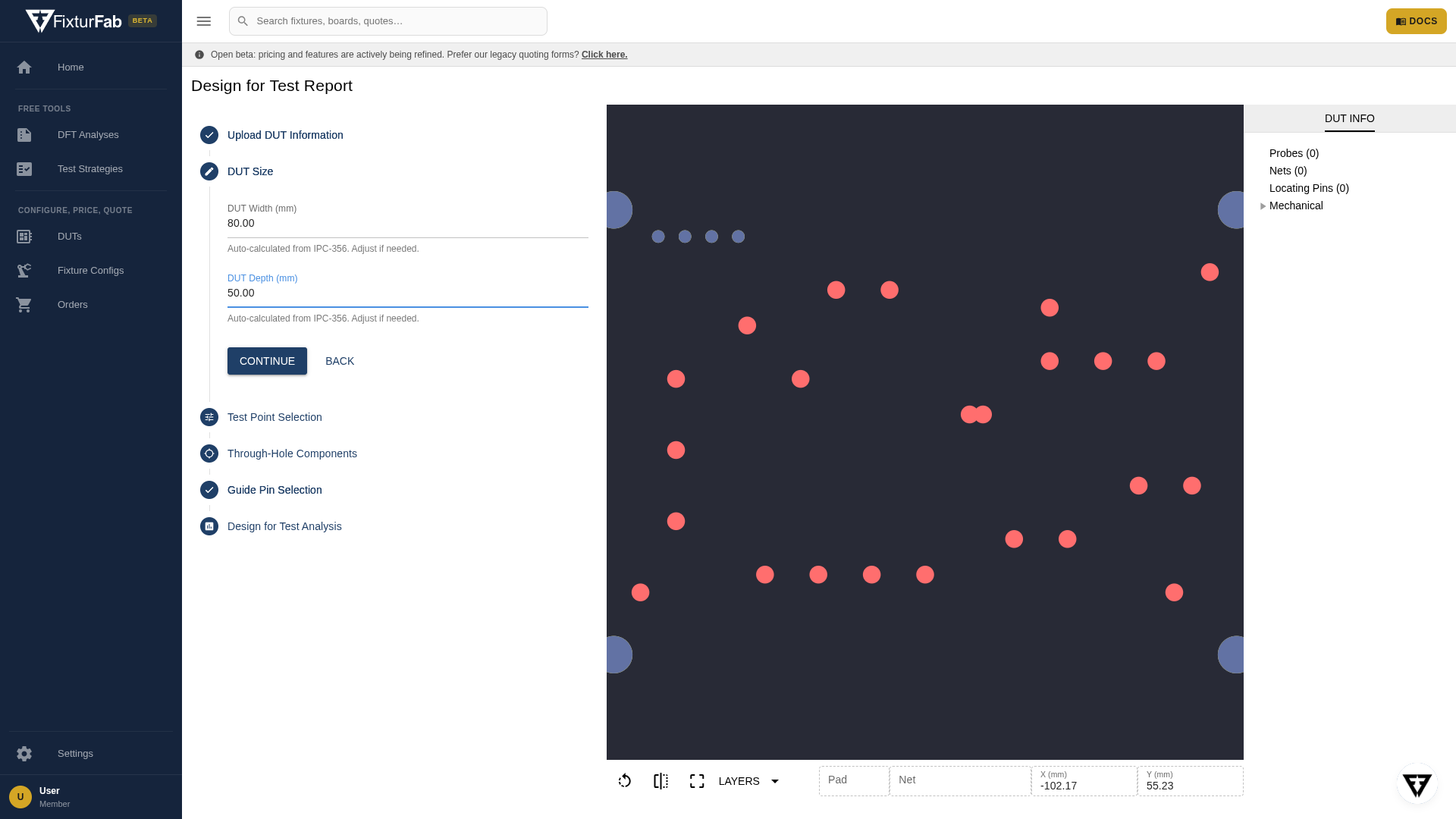
Step 2: DUT Size
The width and depth of the device under test are estimated from the maximum extent of the file's test records — so they will usually read slightly small, since boards extend past their outermost pads.
Update these values if they're not accurate, but feel free to leave them as is if it's still early in your design process.
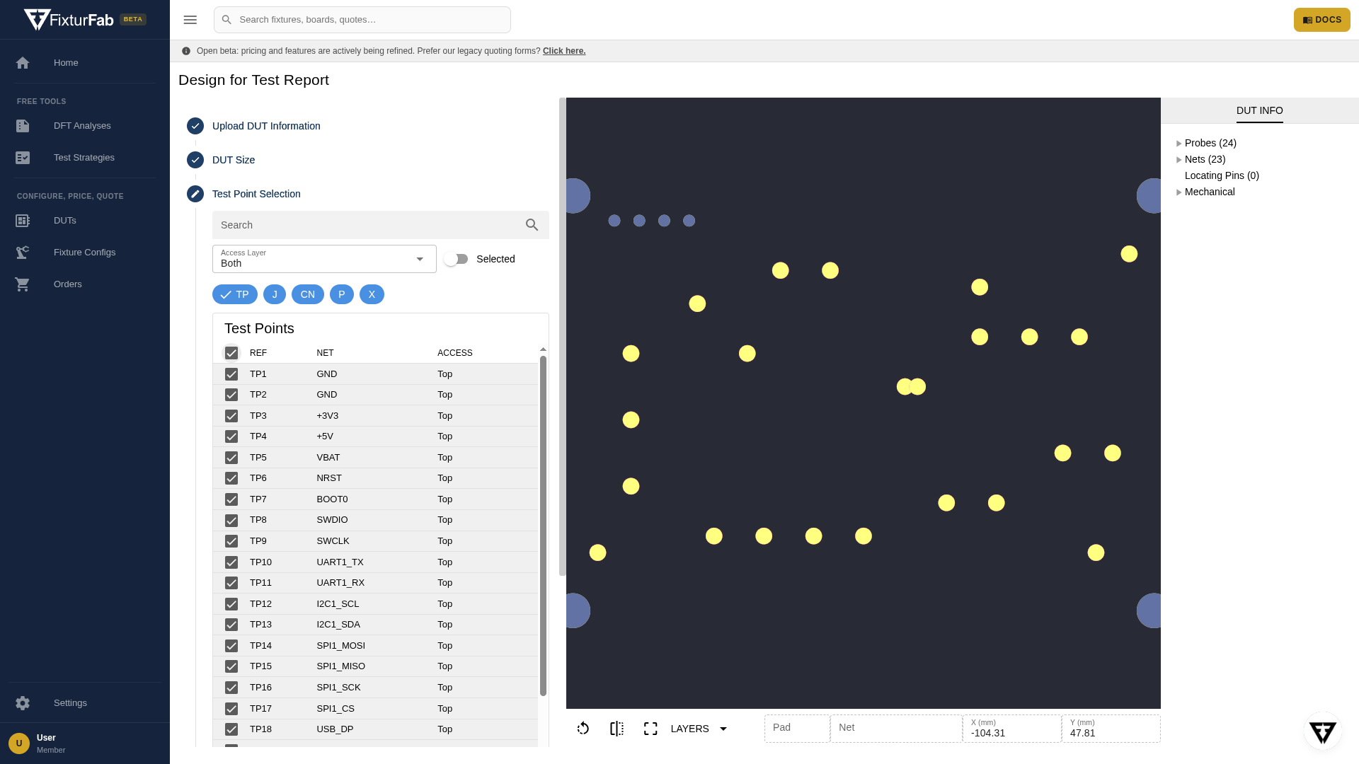
Step 3: Test Point Selection
A table lists all the test records identified in your file. Check the records you want to probe — selected test points are highlighted in the preview in gold.

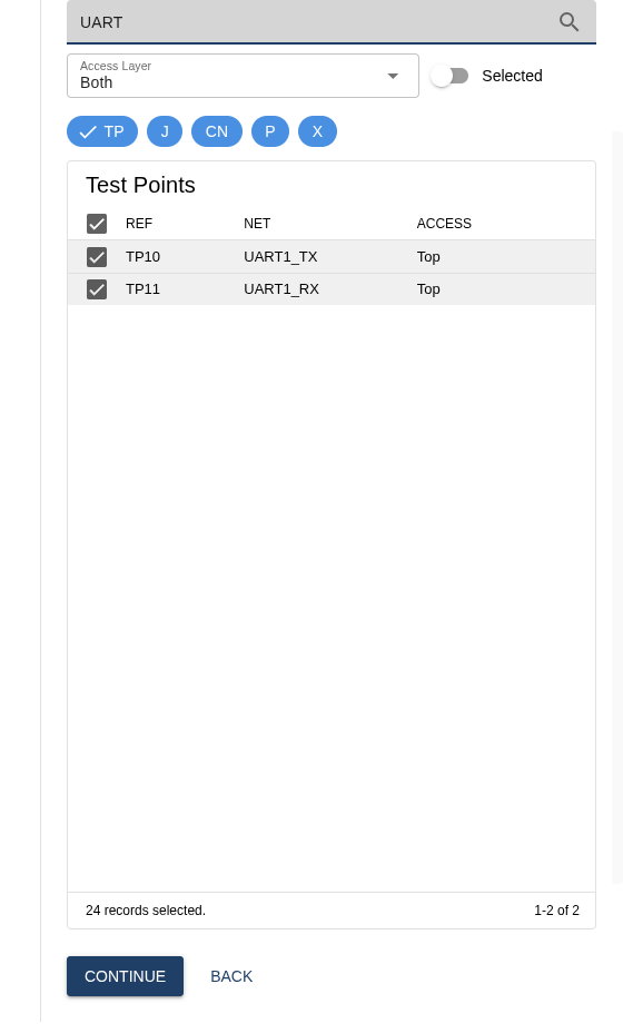
Test point filters
The table can be filtered in several ways:
- Search by reference designator or net name
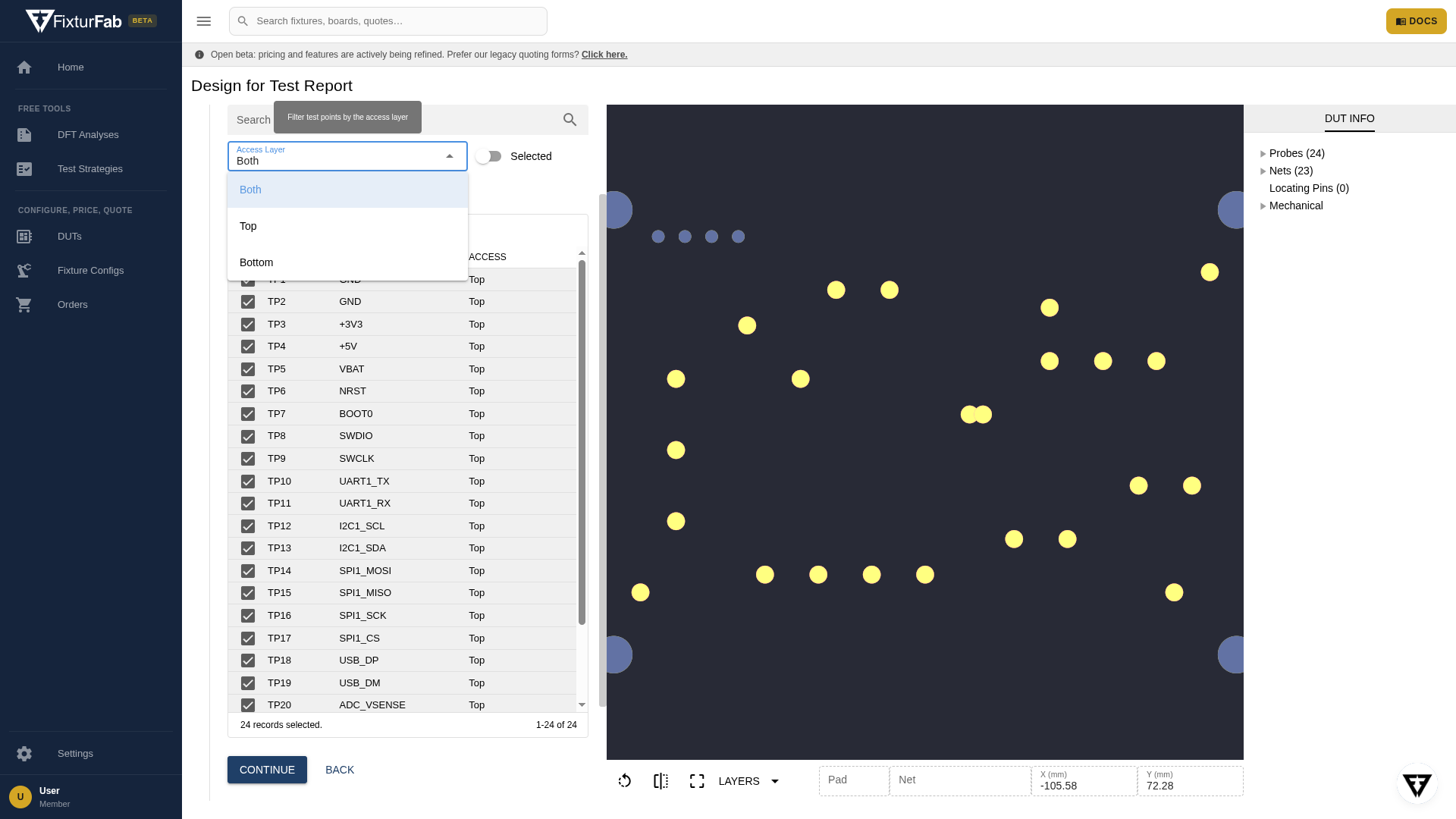
- Filter by the access layer (Top, Bottom, or Both)
- Filter by common reference designator prefixes — TP (test points), J (connectors), CN, P, and X

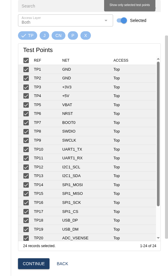
- Show only selected test points with the Selected toggle
TIP
The designator filter defaults to TP, so the table opens showing dedicated test points only. If you want to probe connector pins or other records, enable their designator pill (or deselect all designator pills) before using select-all — select-all only applies to the rows currently shown.
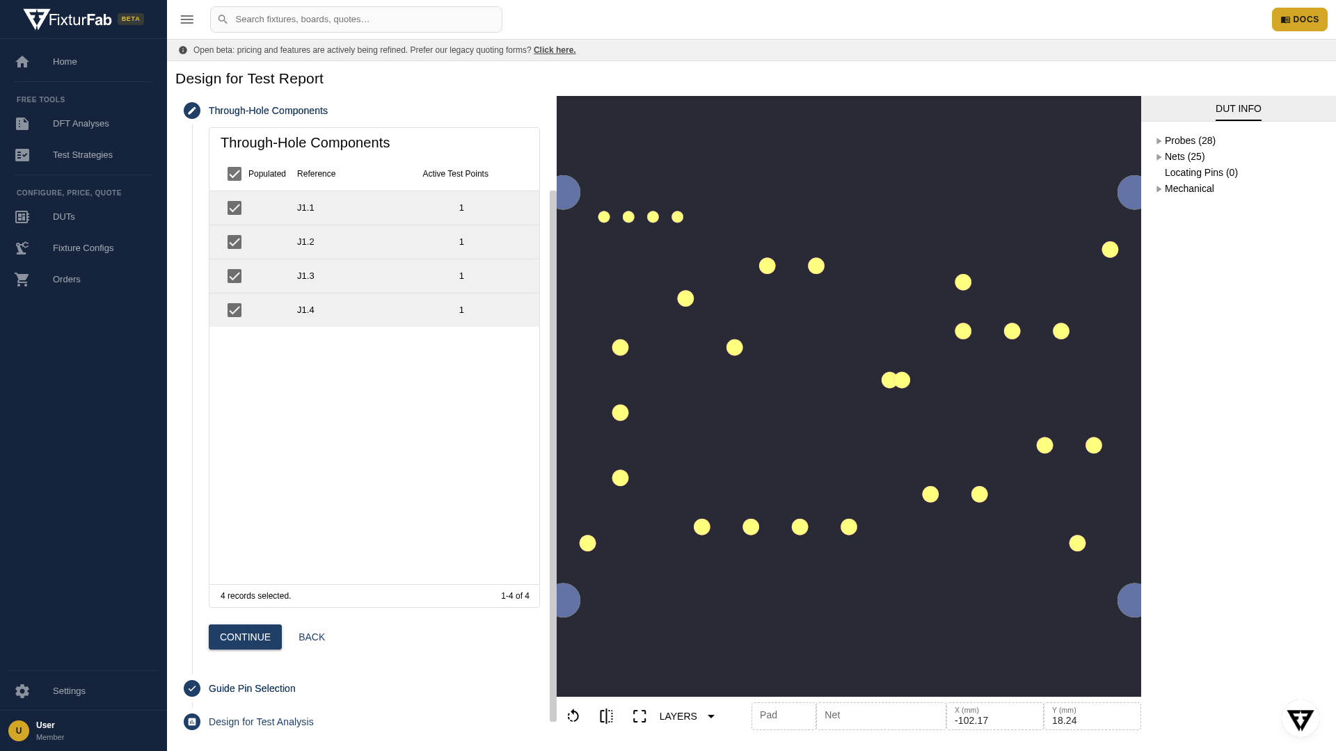
Step 4: Through-Hole Components
If you selected any through-hole records, this step lists their parent components. All through-hole components start as Populated, meaning the component is placed and soldered on the DUT and a "Cup" style test probe will be used.
If a through-hole component will not be populated, deselect it from this table. This identifies that a "Star" style test probe should be used to contact the open barrel.
This step is skipped automatically when no through-hole test points are selected.
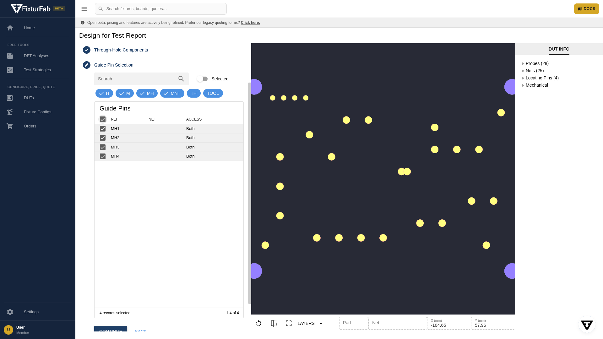
Step 5: Guide Pin Selection
Select the mounting or tooling holes that can be used to locate the DUT. The table defaults to records with common tooling and mounting hole reference designator prefixes — H, M, MH, and MNT (TH and TOOL are also available), and supports the same search and Selected filters as test point selection.
Selected locating holes are shown in the preview in purple.
At least 2 guide pins are needed to locate a DUT. If your board has no usable holes, a locating cradle will be designed instead — see DUT Locating.
Step 6: Design for Test Analysis
An automated analysis of the selected features runs as the final step. Issues are categorized two ways:
- Errors
- High risk issues that could affect manufacturing feasibility and fixture reliability
- Highly recommended to address all of these issues
- Warnings
- Moderate risk issues
- Can affect fixture reliability and/or fixture cost
All issues are shown in the issue tree, grouped by category (pad issues, clearance issues, fixture complexity).
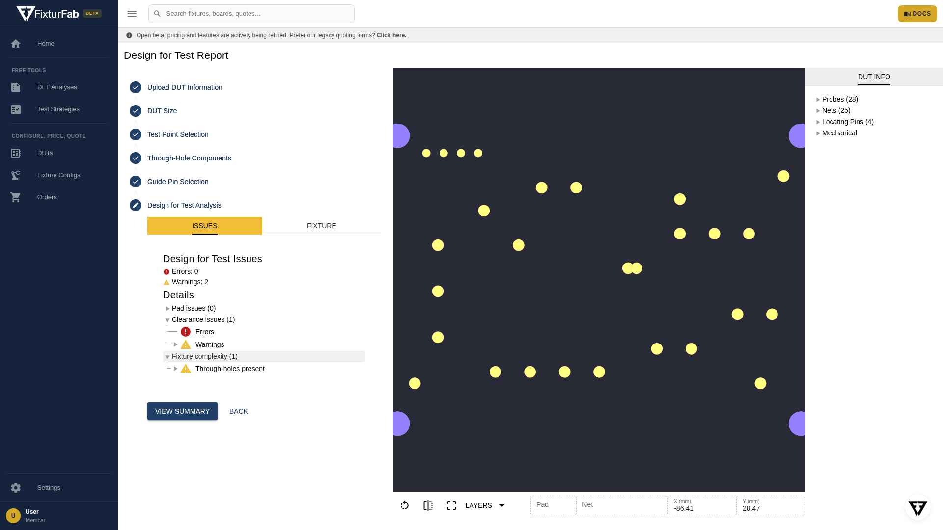
Every rule the analysis runs, with its thresholds, is documented on the design rules page. When you're done reviewing, click View Summary for the full report — see the report summary guide.