FixturIO Controller User's Guide
Overview
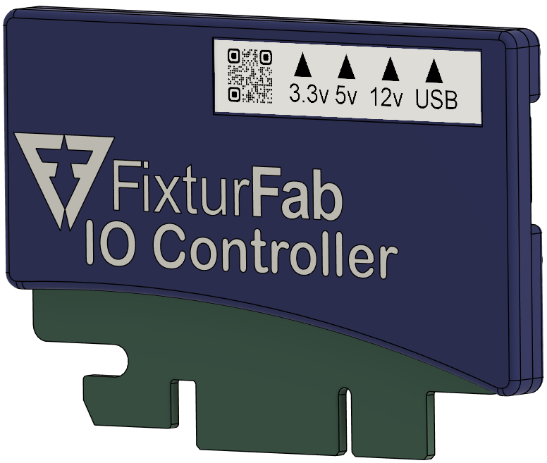
The FixturFab FixturIO Controller is a general purpose digital and analog I/O resource used to implement PCBA test bench control and measurement tasks. It features 37 digital IO pins, 16 of which can be used as ADC (12-bit) analog measurement inputs, 3 independent I2C functions, 9-12V or 5V (USB) power supply options, and a simple to use USB serial API including a python wrapper for easy test software integration in Windows or Linux OS.
The device is based on the Teensy 4.1 MCU board that is designed and manufactured by PJRC (https://www.pjrc.com/store/teensy41.html), featuring an ARM Cortex-M7 processor running at 600MHz. The FixturIO Controller wraps the off-the-shelf Teensy 4.1 board with industrialized I/O circuitry that has hardened ESD and under/over voltage envelope protection, which is more suitable for test system integration where system availability is a key feature. It also provides more power options, allowing 9-12V or 5V (USB) operation, with 3.3V & 5V output supply options to simplify designing other test circuitry in the system.
This is an open source design (hardware, firmware & python wrapper).
Resources and Design Repos:
Typical Applications
- Functional test system instrumentation / general test and measurement
- Relay control (signal muxing, supply muxing, etc.)
- DMM measurements (voltage and/or current via a shunt resistance)
- Interlock control
- Arbitrary digital waveform generation
Hardware Features
- 37 digital I/O pins
- High-density PCIe-style connector
- 4mA continuous output current per pin
- Short-circuit protected
- 16 analog ADC inputs
- 12-bit resolution
- 3.3V rail
- 3 independent I2C bus channels
- (1) Dedicated on card edge connector
- (2) Shared with other GPIO (+ QWIIC connectors for cabled interfaces)
- Industrialized ESD protection on all interfaces
- Under / over voltage protection on all inputs
- 3.3V output rail
- 3.3V-12V input tolerant with series resistor
- Flexible input & output power
- 9V-12V (card edge) or 5V (USB) input supply
- Auto-switching between input supplies (card edge priority)
- 3.3V and 5V regulated output supplies (250mA each)
- Card Identifier pins
- Up to four FixturIO cards in system
- Software device auto-detect based on CardID
Software Features
- Virtualized serial interface over USB
- Tested over millions of interaction cycles per USB enumeration to ensure resiliency in production test environments
- Simple command-line (native) interface
- Open source python wrapper also provided for ease of integration into Windows or Linux OS test runners (open source)
- Native console interface is open source, developed on the Arduino IDE for custom firmware programming if desired.
- Programmable via the built-in USB bootloader
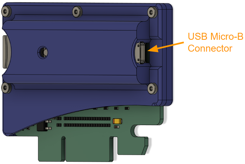
USB Connectivity
Using a USB-A to USB-MicroB cable, the FixturIO Controller is connected to the host system. It supports USB 2.0/Hi-Speed interfaces at 480 Mbps.
The device can be powered off of this USB cable, or, alternatively, can be powered over the edge connector at 9-12V. Power at the edge connector takes precedence over USB power.
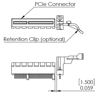
Card Edge Connectivity
The FixturIO Controller uses a standard, high-density PCIe edge connector interface. This allows it to be instantiated in a test system using inexpensive off-the-shelf connectors, such as the following connector and retention clip (retention is recommended, but optional):
Edge Connector: CONN PCI FEMALE 64POS (Samtec Part# PCIE-064-02-F-D-TH)
Retention Clip: CONN ACCESSORY CARD RETENTION (Amphenol Part# 10042618-003LF)
WARNING: the FixturIO edge connector is not electrically or functionally compatible with actual PCIe slots, such as those found on a PC motherboard. Plugging the board into a PCIe slot may result in damage to the FixturIO card as well as the device that it was plugged into.
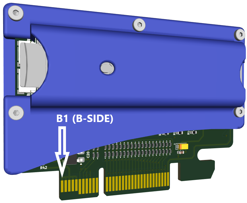
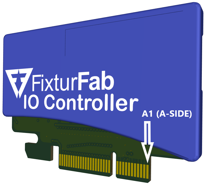
Edge Connector Pin Descriptions
| B-side Pin Function | B-side | A-side | A-side Pin Function |
|---|---|---|---|
| 12V0_IN | B1 | A1 | GND |
| 12V0_IN | B2 | A2 | GND |
| 12V0_IN | B3 | A3 | GND |
| 12V0_IN | B4 | A4 | GND |
| 12V0_IN | B5 | A5 | rsv |
| CARD_ID0 | B6 | A6 | GND |
| CARD_ID1 | B7 | A7 | GND |
| GND | B8 | A8 | I2C_SCL0 |
| GND | B9 | A9 | I2C_SDA0 |
| rsv | B10 | A10 | GND |
| rsv | B11 | A11 | GND |
| NOTCH | NOTCH | ||
| GPIO1 / ADC1 | B12 | A12 | GPIO0 / ADC0 |
| GPIO3 / ADC3 | B13 | A13 | GPIO2 / ADC2 |
| GPIO5 / ADC5 | B14 | A14 | GPIO4 / ADC4 / SDA2 (QWIIC#2) |
| GPIO7 / ADC7 | B15 | A15 | GPIO6 / ADC6 / SCL2 (QWIIC#2) |
| GPIO9 / ADC9 | B16 | A16 | GPIO8 / ADC8 |
| GPIO11 / ADC11 / SDA1 (QWIIC#1) | B17 | A17 | GPIO10 / ADC10 / SCL1 (QWIIC#1) |
| GPIO13 / ADC13 | B18 | A18 | GPIO12 / ADC12 |
| GPIO15 / ADC15 | B19 | A19 | GPIO14 / ADC14 |
| GPIO17 | B20 | A20 | GPIO16 |
| GPIO19 | B21 | A21 | GPIO18 |
| GPIO21 | B22 | A22 | GPIO20 |
| GPIO23 | B23 | A23 | GPIO22 |
| GPIO25 | B24 | A24 | GPIO24 |
| GPIO27 | B25 | A25 | GPIO26 |
| GPIO29 | B26 | A26 | GPIO28 |
| GPIO31 | B27 | A27 | GPIO30 |
| GPIO33 | B28 | A28 | GPIO32 |
| GPIO35 | B29 | A29 | GPIO34 |
| HEARTBEAT | B30 | A30 | GPIO36 |
| GND | B31 | A31 | GND |
| 5V0_OUT (≤250mA) | B32 | A32 | 3V3_OUT (≤250mA) |
GPIO Pin Functions
There are 37 general-purpose I/O pins (GPIO0-GPIO36) that can be programmed individually as digital outputs or inputs. As outputs, they drive to the 3.3V power rail, and can supply up to 4mA per pin. As digital inputs, they are natively 3.3V, but are voltage tolerant up to 12V with a series resistor (see "ESD & Voltage Protections"). Additionally, weak pullup or pulldown resistors can be programmatically attached to any particular input pin.
Each GPIO pin has an associated 169 Ohm series resistor, which limits current during shorting events, provides enhanced ESD inrush performance, and also allows for the direct connection to a LED without any additional series resistance in many cases (depending on LED parametrics).
The GPIO pins default to input orientation with a weak pulldown after powerup or software reset.
Analog Pin Functions
There are 16 analog-capable I/O pins (ADC0-ADC15) that can be read with a 12-bit ADC. To take an ADC reading on a particular pin, it must be configured as an input. The ADC reference voltage is 3.3V, so this is the highest voltage that can be measured without an associated resistor divider circuit.
It is usually good design practice to average over successive ADC readings to remove ambient circuit noise.
I2C Interfaces
I2C is a two-wire serial communication protocol using a serial data line (SDA) and a serial clock line (SCL). The popular protocol supports multiple target devices on a shared communication bus that is routed from device to device in a multi-drop topology.
The FixturIO Controller can be programmed to be an I2C master on three independent buses. One of these interfaces is dedicated to I2C functionality in the edge connector pinout (#0 Bus), the other two share GPIO pin functions, and are also routed to QWIIC connectors on the side of the card (#1, #2 Buses).
Each of the I2C buses can independently be set to run at these supported standard data rates:
- Standard mode: 100 kbit/s
- Fast mode: 400 kbit/s
- Fast mode plus: 1 Mbit/s
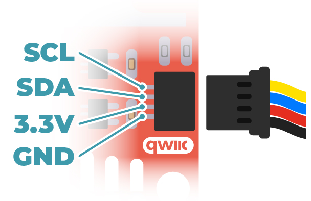
QWIIC Connectors
QWIIC is a quasi-standardized I2C interface (connector, pinout, and cabling) promoted by Sparkfun (www.sparkfun.com) and Adafruit (www.adafruit.com), providing convenient connectivity to their respective lines of interface cards, sensors, and other peripherals. Two QWIIC compatible connectors available on board for I2C peripheral connectivity.
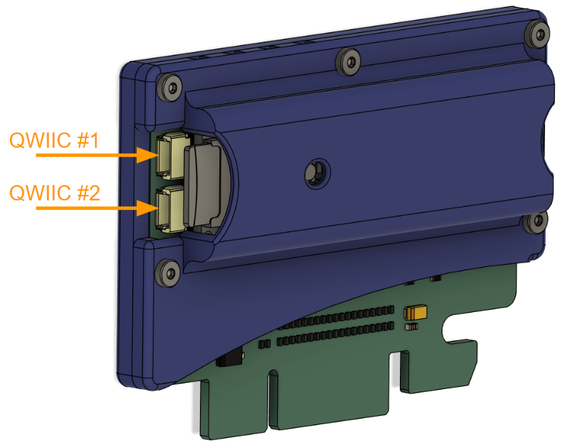
When QWIIC connectors are in use, associated GPIO on the card edge interface should not be used for any other purpose.
Compatible Header Parts
- SMT SM04B-SRSS-TB (white / horizontal)
- SMT BM04B-SRSS-TB (white / vertical)
Compatible Cable Parts
- JST SHR-04V-S-B (housing)
- JST SSH-003T-PO2H (clips)
ESD & Voltage Protections
The FixturIO Controller has industrialized / hardened signal inputs. ESD protection is provided in successive layers, each playing a role in dissipating the tremendous energy released on the circuit in the event of an ESD strike.
Additionally, it is common it test systems to have signaling occurring on a variety of power supplies, so it is desirable to support GPIO inputs that are tolerant of voltages that are higher than those native to the MPU (3.3V for the FixturIO Cortex processor). This voltage conditioning circuitry has the added benefit of improving the overall ESD protection.
The architecture on the input protection circuitry is illustrated in the following diagram.
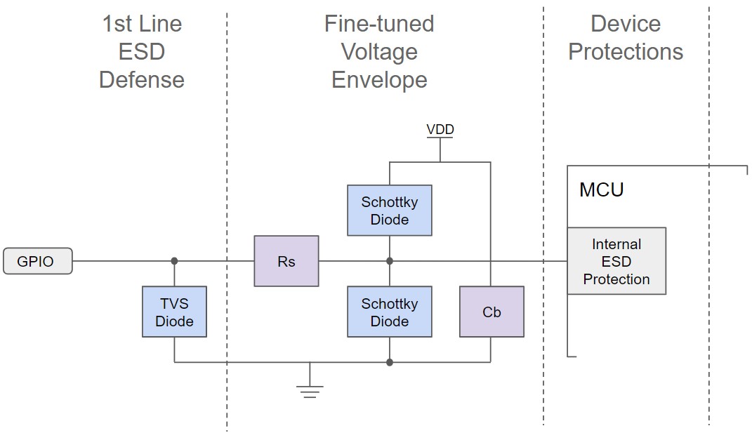
What is a Transient Voltage Suppression (TVS) Diode?
As shown in the circuit, the first line of defense is a TVS diode, which is a specialized device designed specifically for ESD protection. It serves as a bi-directional shunt that responds to very large voltage input in either direction. For lower, signal-level voltages, the device is largely benign (other than adding a small amount of parasitic capacitance to the circuit).
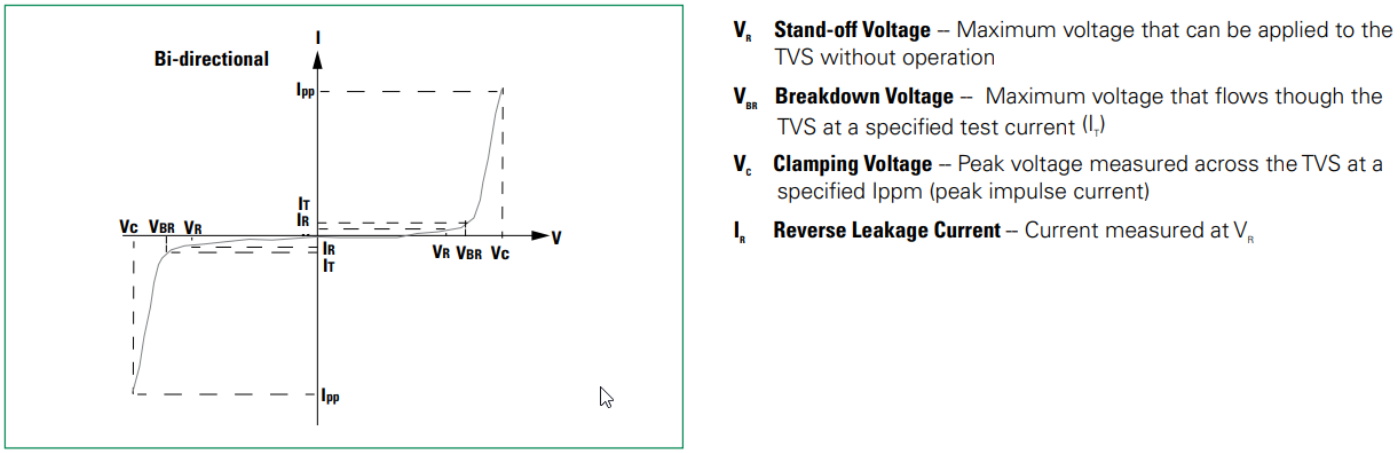
In addition to the active participation of the TVS diode to control unwanted voltages, this design uses a series resistance (Rs) to slow the "impulse" pulse-width for downstream components (reducing instantaneous power during an ESD strike). This series resistance also limits peak GPIO current when the GPIO pin is configured as an output.
Note that this ESD circuit topology requires sufficient, high-quality (low ESR) bypass capacitance present in the power supply (Cb) to convey ESD energy from the ESD diode to the device power supply rather than the MCU component.
As a last line of defense, the MCU has its own internal ESD protection circuit that can eliminate any remaining ESD energy that manages to make it all the way to the device. These internal diodes are not as robust as the upstream protection components, however.
Voltage Envelope Protection
Two Schottky diodes serve to refine the voltage profile of signals presented to the MCU. They "clamp" the input signal to the positive and negative voltage rails to within ~300mV. This provides voltage tolerance for signals that originate from power supply domains that are higher than 3.3V, without the need to level-shift on the periphery of FixturIO.
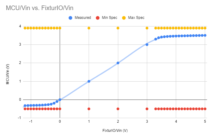
Any signaling level from 3.3V-12V can be accommodated with an appropriately sized series resistance (which limits the current shunted via the diodes). This table summarizes typical system voltages and the minimum series resistance required.
| Signal Voltage | Rseries |
|---|---|
| 3.3V | None Required |
| 5V | None Required |
| 9V | ≥ 402 Ohm |
| 12V | ≥ 698 Ohm |
Note that larger series resistance values should be used if the total amount of current (for all signals) clamped to the power supply exceeds 100mA for all connected signals > 3.3V.
Clamp_Current = (Input_Signal_Volts - 3.3V) / (Rseries + 169 Ohms)
Power Supplies
The FixturIO board can be powered by 12V (a commonly available test system voltage), or by 5V via the USB connection. In either case, there are 5V_OUT and 3.3V_OUT supplies that can be used for other related circuitry in the test system, as long as the current requirements do not exceed 250mA per supply.
In the situation where the 12V supply is energized (via 12V0_IN pins), it is prioritized over the USB supply. Note that the input power supplies can be switched "on-the-fly" without causing the unwanted side-effect of a device reset or reboot event.
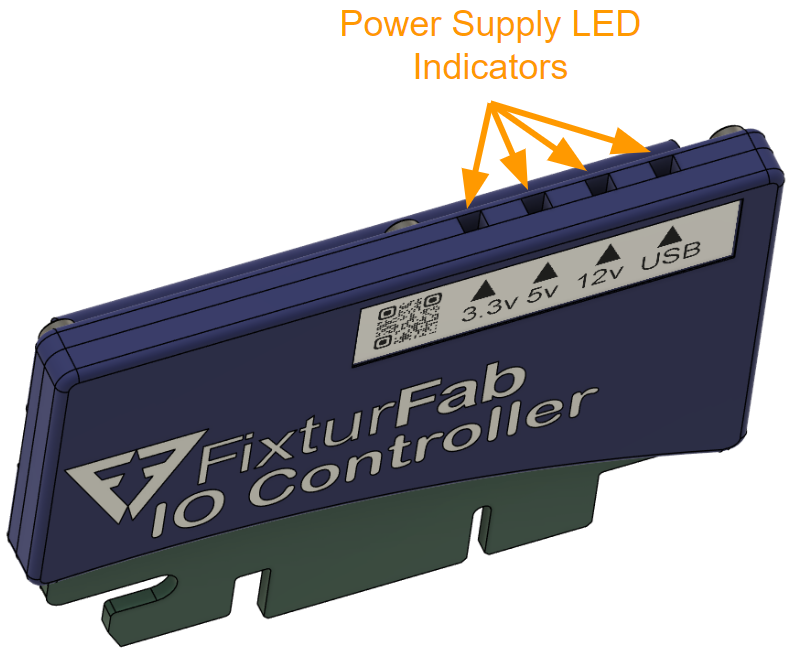
LEDs reflecting the current state of the various power inputs and outputs are located on the top of the case, with labels on the side, as shown.
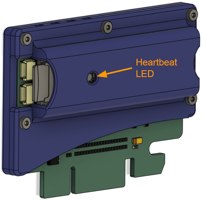
Heartbeat Function
As an indication that the FixturIO card is operating properly, a "heartbeat" LED pulses at a regular interval when the card is powered up, initialized, and servicing it's serial console interface (if connected to USB port).
The HEARTBEAT pin on the edge connector can be used by a test system designer to export this LED function to a place in the system where it is more visible to the user, if desired. If implemented, the external heartbeat LED should have a series resistor limiting the current consumption to ~2mA.
Card Identifier Number
Sometimes it is necessary to instantiate more than one FixturIO Controller in the same test system (due to test requirements). In these cases, it is very useful to identify each controller with a unique Card Identifier Number (CardID) so that the software can easily determine which card is which in the system enumeration and attach the correct test resources.
The FixturIO Controller has two pins on the edge connector for this identification, CARD_ID0 & CARD_ID1. Using these, up to four FixturIO Controllers can coexist in the same test system with no ambiguity regarding their function in the test plan. The test system software reads this parameter during the auto-discovery process that is included with the python wrapper.
If the CARD_ID[1:0] pins are left floating, they default to zero (CARD_ID = 0x0).
| FixturIO# | CARD_ID[1:0] |
|---|---|
| 1 (default) | 0x0 |
| 2 | 0x1 |
| 3 | 0x2 |
| 4 | 0x3 |
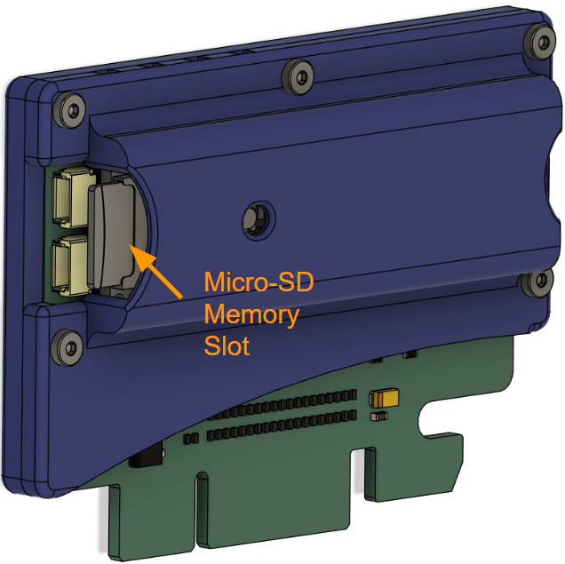
Micro-SD Slot
The memory card slot located above the QWIIC connectors is not currently supported over the FixturIO Controller APIs. However, the feature is supported in the Arduino IDE ("SD Library") if the functionality is desired for your own custom firmware project.
Customizing Firmware
The firmware that ships with the FixturIO Controller implements a simple set of low-level commands that allow access to GPIO, ADC channels, etc. — and these are accessed via a USB Serial Port endpoint, which enumerates into a Windows or Linux OS when the card attached with a USB cable. Written in the Arduino IDE, the firmware is open source, and can be a good starting point for customized firmware that you write for your own project(s).
You can find the firmware repository here.
The FixturIO Controller is built with the PJRC Teensy 4.1 microcontroller board. Valuable programming information can be found at https://www.pjrc.com/store/teensy41.html.
Supported IDEs
Arduino IDE
Arduino's IDE software is the primary (free) programming environment for Teensy.
Visual Micro
Visual Micro allows use of Microsoft Visual Studio to program Arduino compatible boards, including Teensy.
PlatformIO
PlatformIO IDE is a cross platform development environment with many advanced features.
Some Additional Programing Details
Generally, programming the FixturIO Controller's Teensy 4.1 device is handled automatically by the Arduino IDE, which automatically runs the Teensy Loader as needed after your code has been successfully compiled.
If code previously written to the board is not listening for USB communication (a bug has been introduced, or the code is corrupt in some way), automatic entry to programming mode may not be possible. A physical pushbutton is provided to allow recovery from this situation — pressing it returns the board to programming mode, and the Teensy Loader will be able to resume communication.
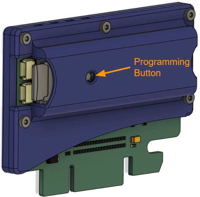
WARNING: if the programming button is pressed during normal operation, the card will stop execution of the main program and go into programming mode. Without communication to the program loader, the card will need to be power cycled to resume the main program. For this reason, the button has been recessed to avoid accidental activation.
Programming Interfaces
Serial Console over USB
When the USB interface is connected to a computer, it enumerates in the system as a virtualized serial device (COM port on Windows, /dev/ttyXYZ on Linux). Any serial terminal application can be used to connect to the native serial console. Typically, default serial interface parameters for baud-rate, handshaking, etc., work fine to connect to the FixturIO Controller.
Note that the FixturIO serial console does not echo input characters, so set the terminal application to "echo" mode to see what you're typing.
Console Protocol & Error Checking
Console input is limited to 128 bytes per line, and any lines that exceed this length are truncated. Command arguments are strictly checked to ensure graceful operation regardless of malformed input.
- The number of arguments are checked for each command ensuring that there are not too few or too many than expected.
- Integer arguments are checked for valid data ranges (i.e. GPIO pin#s, ADC pin#s, etc.) in all cases.
- String arguments are checked for an exact match.
- There are no default arguments, to avoid side effects from future firmware updates.
If a command is properly formed, the console will execute the command and return the result (if applicable), lastly printing "OK" on the next line to indicate that everything was valid.
Example OK Command
> who

[101-0339-01] FixturFab FixturIO Controller (Firmware: Rev 3), CardID = 0

OK
If a command causes an error, the console will print "KO - <ERROR MESSAGE>" on the next line.
Example KO Command
> ioset 37 1

KO - ioset pin number out of range (0-36)
This "OK" and "KO" acknowledgement to each command facilitates a consistent, tight loop protocol with the code that is issuing the commands, to sidestep "loss of context" problems that can arise with serial stream communications, crashing test systems in some cases that are difficult to debug.
Serial Console Commands
| Command | Arguments | Returns | Description |
|---|---|---|---|
| help | none | multi-line list of str | Prints a list of recognized commands and associated argument information. |
| who | none | str | Returns device part#, manufacturer, firmware rev, & card identifier. |
| fw | none | int | Returns device firmware version |
| mfg | none | str | Returns device manufacturer (i.e. "FixturFab") |
| mpn | none | str | Returns device part number (i.e. "101-0339-01") |
| card | none | int | Returns device card identifier (0-3) |
| ioset | pin# (int), value (int) | none | Sets GPIO output pin# to value (1 or 0). Pin must be previously set to be an output type using "iotype" command. |
| ioall | value (int) | none | Sets all GPIO output pins to value (1 or 0). Pins must be previously set to be an output type using "iotype" command. |
| ioget | pin# (int) | int | Returns the current state of GPIO pin# (1 or 0). Pin orientation would normally be configured as an input, but works on output pins also. |
| iotype | pin# (int), | ||
| out | in | inpu | inpd (str) |
| adc | pin# (int) | int | Returns the 12-bit ADC reading of Analog pin# (i.e. 0-4095). |
| i2c_cntl | bus# (int), | ||
| enable | disable (str) | none | Sets target I2C bus# (0 |
| i2c_clk | bus# (int), | ||
| standard | fast | fast+ (str) | none |
| standard = 100KHz / fast = 400KHz / fast+ = 1MHz | |||
| i2c_hello | bus# (int), | ||
| address (int) | int | Pokes I2C bus# (0 | 1 |
| i2c_write | bus# (int), address (int), reg# (int), data (int) | none | Writes data byte (0-255) to I2C bus# (0 |
| i2c_read | bus# (int), address (int), reg# (int) | int | Reads data byte (0-255) from I2C bus# (0 |
| reset | none | none | Performs a hard reset on the board. Connection to serial interface will be lost. |
Python Wrapper
A Python wrapper is available within the open source f3ts-hardware-utils module. You can view the serial interface directly here.
Recommended Operating Conditions
| Parameter | Conditions/Notes | Min | Typ | Max | Units |
|---|---|---|---|---|---|
| 12V0.Vin | Auxiliary supply input voltage (12V0_IN with reference to GND) | 7.5 | 12 | 15 | V |
| 12V0.Iin | Auxiliary supply current consumption @ Vin = 12V | 150 | mA | ||
| 3V3.Vout | 3.3V supply voltage output (3V3_OUT with reference to GND) | 3.23 | 3.3 | 3.34 | V |
| 3V3.Iout | 3.3V supply current output (2) | 250 | mA | ||
| 5V0.Vout | 5.0V supply voltage output (5V0_OUT with reference to GND) | 4.9 | 5.0 | 5.1 | V |
| 5V0.Iout | 5.0V supply current output (2) | 250 | mA | ||
| GPIO.Vin | Digital input voltage range (1) | -0.2 | 12 | V | |
| GPIO.Vout | Digital output voltage | 3.3 | V | ||
| GPIO.Iout | Digital output current per pin | 4 | mA | ||
| ADC.Vin | Analog input voltage range (to achieve full count range). | 0 | 3.3 | V | |
| ADC.Res | Analog ADC resolution (0 - 4095) | 12 | bits |
(1) Requires appropriate series resistor if amplitude exceeds 5V, see "ESD & Voltage Protections" section for more detail.
(2) Specification is relevant when powered from the auxiliary supply (12V0_IN). When powered by USB, typically the overall current draw is restricted to 500mA per port, so each output supply's current rating may be lower depending on various system-level considerations.
ESD Ratings
| Parameter | Conditions/Notes | Min | Typ | Max | Units |
|---|---|---|---|---|---|
| Vesd | EC 61000-4-2, level 4, contact discharge to edge connector interface | -8 | +8 | kV |